Weider Viper 2000 Uk Manual - Page 10
Attach the Adjustment U Bracket 75 to
 |
View all Weider Viper 2000 manuals
Add to My Manuals
Save this manual to your list of manuals |
Page 10 highlights
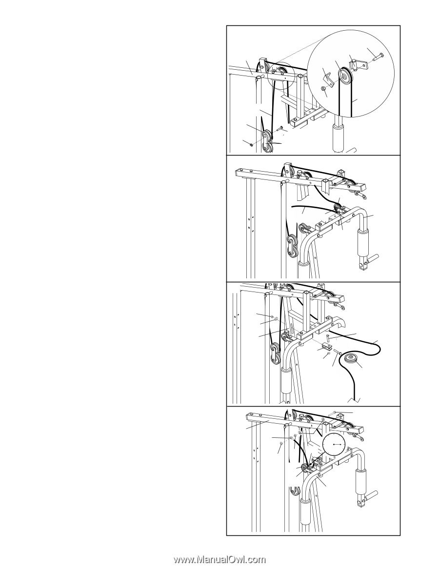
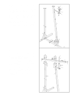
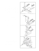
19. Remove the 3/8" Nylon Locknut (21), 3/8" x 1 3/4" Bolt (48), and 4 1/2" Pulley (77) from one end of the "I" Plates (78). Route the Long Cable (66) under the Pulley and reattach the Pulley to the "I" Plates with the Bolt and Nylon Locknut. Refer to the inset drawing. (Note: The Wide Swivel Bracket [71] is attached to the Top Frame [67]; it is shown disassembled for clarity.) Lay the Long Cable (66) over a 3 1/2" Pulley (15). Attach the Pulley and a Cable Trap (59) to the Wide Swivel Bracket (71) with a 3/8" x 1 3/4" Bolt (48) and 3/8" Nylon Locknut (21). Be sure that the Cable Trap is turned to the indicated position. 20. Wrap the Long Cable (66) down around the 3 1/2" Pulley (15) on the left Arm (46). Tighten the 3/8" Nylon Locknut (21) and 3/8" x 1 3/4" Bolt (not shown). Be sure that the Cable Trap (59) is turned to the indicated position. 19 67 66 77 21 20 48 71 15 59 21 66 48 78 15 66 21 46 59 21. Note: The 4 1/2" Pulley (77) shown in this step is preattached to the Adjustment "U" Bracket (75). Attach the Adjustment "U" Bracket (75) to the Front Upright (42) with the 5/16" x 3 1/4" Bolt (35), a 5/16" Flat Washer (8), and a 5/16" Nylon Locknut (3). Thread the Nylon Locknut onto the Bolt only two complete turns. Remove the 3/8" x 1 3/4" Bolt (48), 3/8" Nylon Locknut (21), and 4 1/2" Pulley (77) from the Adjustment "U" Bracket (75). Wrap the Long Cable (66) around the Pulley as shown. Reattach the Pulley to the Adjustment "U" Bracket with the Bolt and Nylon Locknut. 22. Wrap the Long Cable (66) up around the 3 1/2" Pulley (15) on the right Arm (46). Tighten the 3/8" x 1 3/4" Bolt (48) and 3/8" Nylon Locknut (not shown). Be sure that the Cable Trap (59) is turned to the indicated position. Attach the 5/16" x 3" Bolt (17), two 5/16" Flat Washers (8), and a 5/16" Jam Nut (2) to the indicated hole in the Top Frame (67). Slide the end of the Long Cable (66) onto the 5/16" x 3" Bolt (17). Tighten another 5/16" Jam Nut (2) onto the Bolt. 21 3 8 42 75 21 35 48 66 77 22 67 17 66 22 15 48 8 12 9 3 59 6 46 10
-
 1
1 -
2
-
3
-
4
-
 5
5 -
 6
6 -
 7
7 -
 8
8 -
 9
9 -
 10
10 -
 11
11 -
 12
12 -
 13
13 -
 14
14 -
 15
15 -
16
-
17
-
18
-
19
-
20
-
21
-
22
-
23
-
24
-
25
-
26
-
27
 |
 |