Weider Viper 2000 Uk Manual - Page 9
Lay the Long Cable 66 over a 4 1/2 Pulley 77.
 |
View all Weider Viper 2000 manuals
Add to My Manuals
Save this manual to your list of manuals |
Page 9 highlights
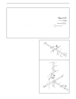
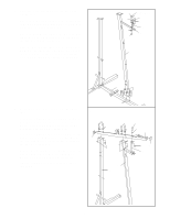
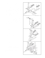
15. Attach the Wide Swivel Bracket (71) to the indi- 15 cated bracket on the Top Frame (67) with a 5/16" x 3 1/4" Bolt (35) and 5/16" Nylon Locknut (3). Do not overtighten the Nylon Locknut; the Wide Swivel Bracket must be able to swivel freely. 35 67 3 71 16. If the parts shown at the right have not been preassembled, follow the instructions below to assemble them. Attach the two "I" Plates (78) to two 4 1/2" Pulleys (77) with two 3/8" x 1 3/4" Bolts (48) and 3/8" Nylon Locknuts (21) as shown. Do not thread the Nylon Locknuts all the way onto the Bolts until assembly step 24 is completed. 16 21 77 48 78 77 78 17. IMPORTANT: As you assemble the Long Cable (66) and the Short Cable (not shown), refer to page 19 of this manual to make sure that the Cables are properly routed. Find the end of the Long Cable (66) that does not have a rubber ball. Insert that end of the Long Cable up through the indicated opening in the Top Frame (67). Lay the Long Cable (66) over a 4 1/2" Pulley (77). Attach the Pulley inside the Top Frame (67) with a 3/8" x 2 3/4" Bolt (70), two 3/8" Flat Washers (9), the two 1/2" x 1/2" Spacers (65), and a 3/8" Nylon Locknut (21). 18. Remove the 3/8" x 1 3/4" Bolt (48), 3/8" Nylon Locknut (21), and 3 1/2" Pulley (15) from the indicated bracket on the Top Frame (67). Insert the end of the Long Cable (66) through the bracket and down through the indicated hole. Reattach the 3 1/2" Pulley (15) to the bracket on the Top Frame (67) with the 3/8" x 1 3/4" Bolt (48) and 3/8" Nylon Locknut (21). Be sure that the Long Cable is between the Pulley and the top of the bracket. 17 66 65 77 65 9 70 21 9 67 18 Bracket Hole 67 21 15 66 48 9
-
 1
1 -
2
-
3
-
 4
4 -
 5
5 -
 6
6 -
 7
7 -
 8
8 -
 9
9 -
 10
10 -
 11
11 -
 12
12 -
 13
13 -
 14
14 -
15
-
16
-
17
-
18
-
19
-
20
-
21
-
22
-
23
-
24
-
25
-
26
-
27
 |
 |
