Weslo 605 Instruction Manual - Page 6
wires are
 |
View all Weslo 605 manuals
Add to My Manuals
Save this manual to your list of manuals |
Page 6 highlights
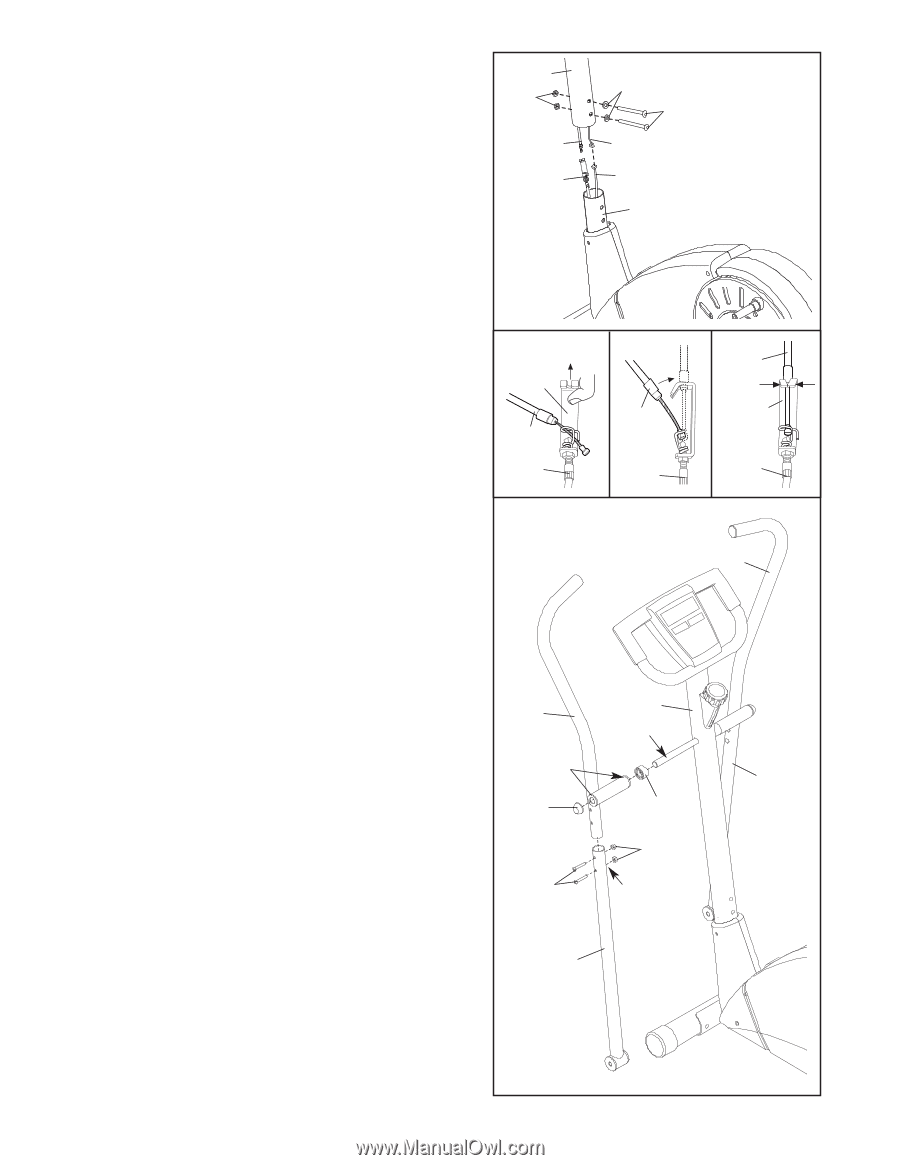
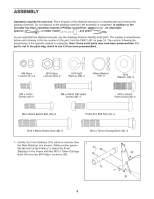
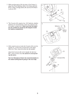
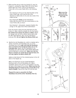
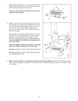
5. While another person holds the Upright (2) near the Frame (1), connect the Upper Wire (44) to the Reed Switch Wire (53). Next, connect the Resistance Cable (45) to the Lower Cable (20) in the following way: • See drawing A. Pull up on the metal bracket on the Lower Cable (20), and insert the tip of the Resistance Cable (45) into the wire clip inside of the metal bracket. • See drawing B. Firmly pull the Resistance Cable (45) and slide it into the metal bracket on the Lower Cable (20) as shown. • See drawing C. Using pliers, squeeze together the prongs on the upper end of the metal bracket. Push the excess cable and wire downward into the Frame (1). Next, slide the Upright (2) onto the Frame. Be careful not to pinch the wires or cables. Attach the Upright with two M10 x 68mm Button Bolts (48), two M10 Split Washers (59), and two M10 Nylon Locknuts (33). Do not tighten the Button Bolts yet. 6. Identify the Left Handlebar (6), which is marked with a sticker. Insert the Left Handlebar into one of the Handlebar Arms (5); make sure that the Handlebar Arm is turned so the hexagonal holes are on the indicated side. Attach the Left Handlebar to the Handlebar Arm with two M6 x 36mm Button Bolts (50) and two M6 Nylon Locknuts (27). Make sure that the Nylon Locknuts are inside the hexagonal holes. Do not fully tighten the Button Bolts yet. Apply a small amount of the included grease to the left axle on the Upright (2). Make sure that there are two Small Handlebar Bushings (49) in the Left Handlebar (6). Slide a Handlebar Spacer (47) and the Left Handlebar onto the left axle on the Upright (2) as shown. Make sure that the Handlebar Spacer is turned so the curved side is facing the Upright. Tap an Axle Cap (14) onto the axle. Repeat this step to assemble the Right Handlebar (8) and the other Handlebar Arm (5). 52 33 45 20 A Metal Bracket 45 20 6 6 49 14 50 59 48 44 Make sure the 53 wires are not pinched during 1 this step. B 45 20 C 45 Metal Bracket 20 8 2 Grease 5 47 27 Hexagonal Holes 5 6
-
 1
1 -
 2
2 -
 3
3 -
 4
4 -
 5
5 -
 6
6 -
 7
7 -
 8
8 -
 9
9 -
 10
10 -
 11
11 -
 12
12 -
13
-
14
-
15
-
16
 |
 |