Weslo Body Shop 9 English Manual - Page 18
Weslo Body Shop 9 Manual
 |
View all Weslo Body Shop 9 manuals
Add to My Manuals
Save this manual to your list of manuals |
Page 18 highlights
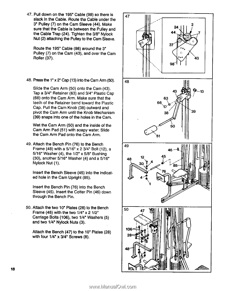
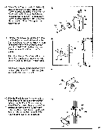
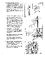
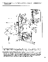
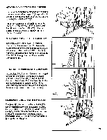
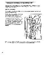
47. Pull down on the 195" Cable (98) so there is 47 slack in the Cable. Route the Cable under the 3" Pulley (7) on the Cam Sleeve (44). Make sure that the Cable is between the Pulley and the Cable Trap (24). Tighten the 3/8" Nylock Nut (2) attaching the Pulley to the Cam Sleeve. Route the 195" Cable (98) around the 3" Pulley (7) on the Cam (43), and over the Cam Roller (37). - - 24 2 44 7 . 37 O ,__O_ . co o ' ... 43 98 •,,, 48. Press the 1" x 2" Cap (13) into the Cam Arm (50). Slide the Cam Arm (50) onto the Cam (43). Tap a 3/4" Retainer (63) and 3/4" Plastic Cap (66) onto the Cam Arm. Make sure that the teeth of the Retainer bend toward the Plastic Cap. Pull the Cam Knob (38) outward and pivot the Cam Arm until the Knob Mechanism (39) snaps into one of the holes in the Cam. Wet the Cam Arm (50) and the inside of the Cam Arm Pad (51) with soapy water. Slide the Cam Arm Pad onto the Cam Arm. 49. Attach the Bench Pin (76) to the Bench Frame (48) with a 5/16" x 2 3/4" Bolt (12), a 5/16" Washer (4), the 1/2" x 5/8" Bushing (30), another 5/16" Washer (4) and a 5/16" Nylock Nut (1). Insert the Bench Sleeve (45) into the indicated hole in the Cam Upright (85). Insert the Bench Pin (76) into the Bench Sleeve (45). Insert the Cotter Pin (46) down through the Bench Pin. 50. Attach the two 10" Plates (28) to the Bench Frame (48) with the two 1/4" x 2 1/2" Carriage Bolts (106), two 1/4" Washers (5) and two 1/4" Nylock Nuts (3). Attach the Bench (47) to the 10" Plates (28) with four 1/4" x 3/4" Screws (8). 48 43 1----13 63 66 --•''. VIII, :::i. 38 39 .- 50 51 49 46 -4. , 48 12 45 30)1 4 -II). - 76 .. 4.1 \ --, --- f 1 4 . 50 47 . --- ! i 106 . 28 I I 0. 48 ' 5 .., .....- . 18 - ..!.
-
 1
1 -
2
-
3
-
4
-
5
-
6
-
7
-
8
-
9
-
10
-
11
-
12
-
 13
13 -
 14
14 -
 15
15 -
 16
16 -
 17
17 -
 18
18 -
 19
19 -
 20
20 -
 21
21 -
 22
22 -
 23
23 -
24
 |
 |