Weslo Body Shop 9 English Manual - Page 4
Assembly
 |
View all Weslo Body Shop 9 manuals
Add to My Manuals
Save this manual to your list of manuals |
Page 4 highlights
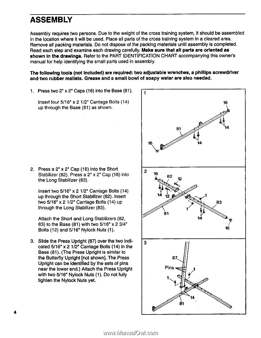
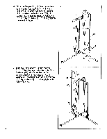
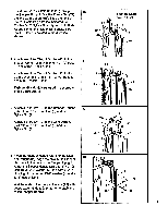
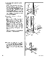
ASSEMBLY Assembly requires two persons. Due to the weight of the cross training system, it should be assembled in the location where it will be used. Place all parts of the cross training system in a cleared area. Remove all packing materials. Do not dispose of the packing materials until assembly is completed. Read each step and examine each drawing carefully. Make sure that all parts are oriented as shown in the drawings. Refer to the PART IDENTIFICATION CHART accompanying this owner's manual for help identifying the small parts used in assembly. The following tools (not Included) are required: two adjustable wrenches, a phillips screwdriver and two rubber mallets. Grease and a small bowl of soapy water are also needed. 1. Press two 2" x 2" Caps (16) into the Base (81). 1 Insert four 5/16" x 2 1/2" Carriage Bolts (14) 16 up through the Base (81) as shown. 81 14 16 14 2. Press a 2" x 2" Cap (16) into the Short Stabilizer (82). Press a 2" x 2" Cap (16) into the Long Stabilizer (83). Insert two 5/16" x 2 1/2" Carriage Bolts (14) up through the Short Stabilizer (82). Insert two 5/16" x 2 1/2" Carriage Bolts (14) up through the Long Stabilizer (83). Attach the Short and Long Stabilizers (82, 83) to the Base (81) with two 5/16" x 2 3/4" Bolts (12) and 5/16" Nylock Nuts (1). 3. Slide the Press Upright (87) over the two indicated 5/16" x 2 1/2" Carriage Bolts (14) in the Base (81). (The Press Upright is similar to the Butterfly Upright [not shown]. The Press Upright can be identified by the sets of pins near the lower end.) Attach the Press Upright with two 5/16" Nylock Nuts (1). Do not fully tighten the Nylock Nuts yet. 2 16 82 12 14 2 81 1 14 3 87 Pins 4/1 1 83 16 14 81 4
-
 1
1 -
 2
2 -
 3
3 -
 4
4 -
 5
5 -
 6
6 -
 7
7 -
 8
8 -
 9
9 -
 10
10 -
11
-
12
-
13
-
14
-
15
-
16
-
17
-
18
-
19
-
20
-
21
-
22
-
23
-
24
 |
 |