Whirlpool SF265LXTT Installation Instructions - Page 14
To Convert, Standard, Surface, Burners, Burner, Natural Gas Orifice Spud Chart, Surface Burners,
 |
UPC - 883049054919
View all Whirlpool SF265LXTT manuals
Add to My Manuals
Save this manual to your list of manuals |
Page 14 highlights
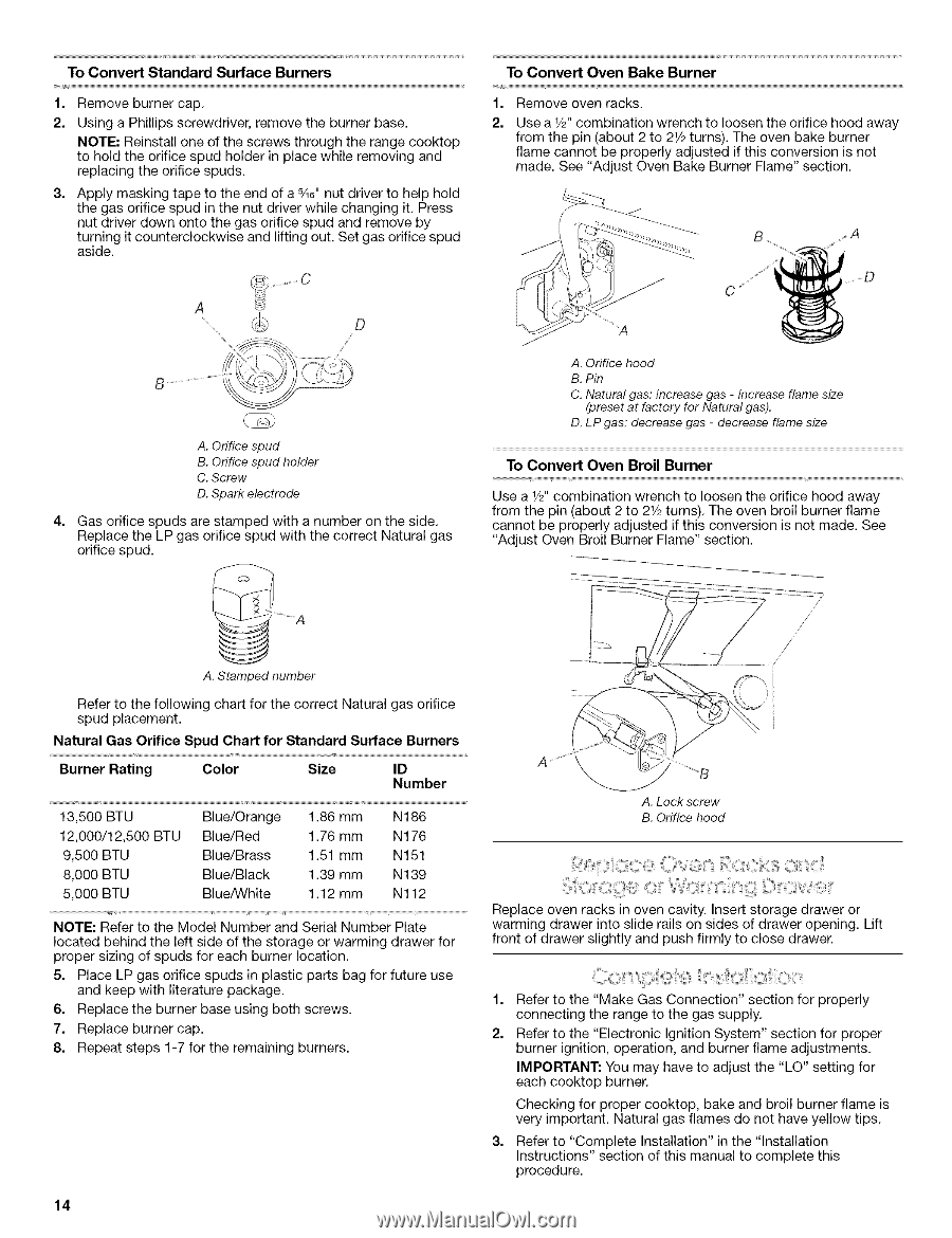
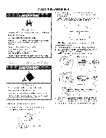
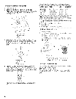
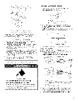
To Convert Standard Surface Burners 1. Remove burner cap. 2. Using a Phillips screwdriver, remove the burner base. NOTE: Reinstall one of the screws through the range cooktop to hold the orifice spud holder in place while removing and replacing the orifice spuds. 3. Apply masking tape to the end of a _6" nut driver to help hold the gas orifice spud in the nut driver while changing it. Press nut driver down onto the gas orifice spud and remove by turning it counterclockwise and lifting out. Set gas orifice spud aside. A To Convert Oven Bake Burner 1. Remove oven racks. 2. Use a 1/2"combination wrench to loosen the orifice hood away from the pin (about 2 to 21/2turns). The oven bake burner flame cannot be properly adjusted if this conversion is not made. See "Adjust Oven Bake Burner Flame" section. f -- C A. Orifice spud B. Orifice spud holder C. Screw D. Spark electrode 4= Gas orifice spuds are stamped with a number on the side. Replace the LP gas orifice spud with the correct Natural gas orifice spud. A. Orifice hood B. Pin C. Natural gas: increase gas - increase flame size (preset at factory for Natural gas). D. LP gas: decrease gas - decrease flame size To Convert Oven Broil Burner Use a 1/2"combination wrench to loosen the orifice hood away from the pin (about 2 to 21/2turns). The oven broil burner flame cannot be properly adjusted if this conversion is not made. See "Adjust Oven Broil Burner Flame" section. A. Stamped number Refer to the following chart for the correct Natural gas orifice spud placement. Natural Gas Orifice Spud Chart for Standard Surface Burners Burner Rating Color Size ID Number 13,500 BTU 12,000/12,500 BTU 9,500 BTU 8,000 BTU 5,000 BTU Blue/Orange Blue/Red Blue/Brass Blue/Black Blue/White 1.86 mm 1.76 mm 1.51 mm 1.39 mm 1.12 mm N186 N 176 N151 N139 N112 NOTE: Refer to the Model Number and Serial Number Plate located behind the left side of the storage or warming drawer for proper sizing of spuds for each burner location. 5. Place LP gas orifice spuds in plastic parts bag for future use and keep with literature package. 6. Replace the burner base using both screws. 7. Replace burner cap. 8. Repeat steps 1-7 for the remaining burners. 14 / J / A. Lock screw B. Orifice hood Replace oven racks in oven cavity. Insert storage drawer or warming drawer into slide rails on sides of drawer opening. Lift front of drawer slightly and push firmly to close drawer. 1. Refer to the "Make Gas Connection" section for properly connecting the range to the gas supply. 2. Refer to the "Electronic Ignition System" section for proper burner ignition, operation, and burner flame adjustments. IMPORTANT: You may have to adjust the "LO" setting for each cooktop burner. Checking for proper cooktop, bake and broil burner flame is very important. Natural gas flames do not have yellow tips. 3. Refer to "Complete Installation" in the "Installation Instructions" section of this manual to complete this procedure.
-
 1
1 -
2
-
3
-
4
-
5
-
6
-
7
-
8
-
 9
9 -
 10
10 -
 11
11 -
 12
12 -
 13
13 -
 14
14 -
 15
15 -
 16
16
 |
 |