Whirlpool SF265LXTT Installation Instructions - Page 8
isopenwhen
 |
UPC - 883049054919
View all Whirlpool SF265LXTT manuals
Add to My Manuals
Save this manual to your list of manuals |
Page 8 highlights
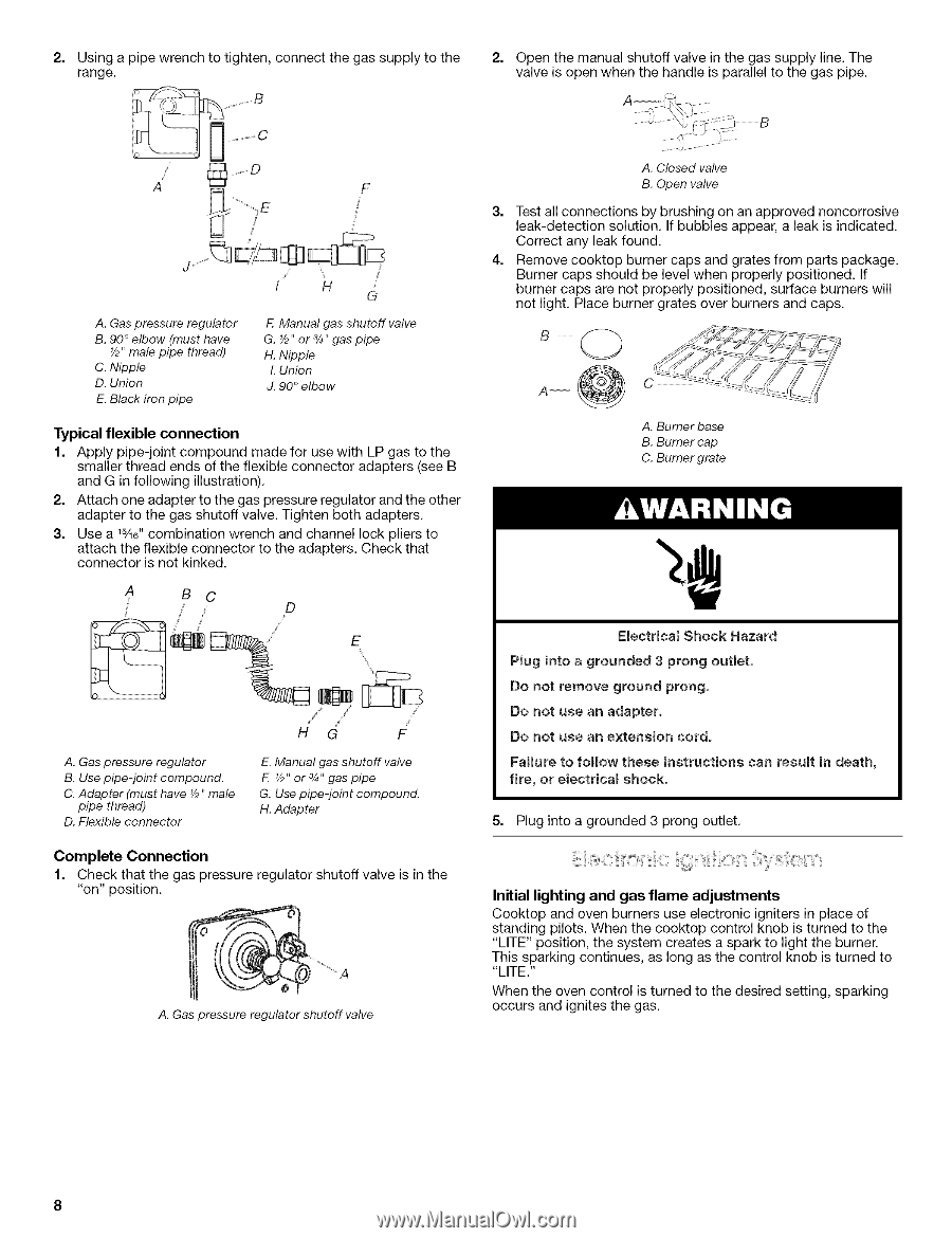
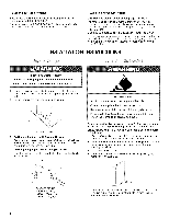
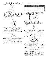
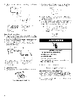
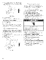
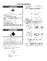
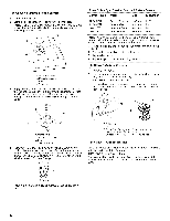
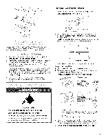
2. Usinga pipewrencthotightenc,onnectht egassuppltyothe 2. Openthemanuaslhutovffalveinthegassuppllyine.The range, valveisopenwhenthehandleisparalletol thegaspipe. / A F ?E ii' A. Gas pressure regulator B. 90 ° elbow (must have Yp" male pipe thread) C. Nipple D. Union E. Black iron pipe f H G F Manual gas shutoff valve G. Y2" or 3/4,,gas pipe H. Nipple L Union J. 90 ° elbow Typical flexible connection 1. Apply pipe-joint compound made for use with LP gas to the smaller thread ends of the flexible connector adapters (see B and G in following illustration). 2. Attach one adapter to the gas pressure regulator and the other adapter to the gas shutoff valve. Tighten both adapters. 3. Use a 1%6" combination wrench and channel lock pliers to attach the flexible connector to the adapters. Check that connector is not kinked. A BC D _ E A. Gas pressure regulator B. Use pipe-joint compound. C. Adapter (must have Y2"male pipe thread) D. Flexible connector HG F E. Manual gas shutoff valve F. V2" or 3/4"gas pipe G. Use pipe-joint compound. H. Adapter Complete Connection 1. Check that the gas pressure regulator shutoff valve is in the "on" position. _ A A. Gaspressure regulator shutoff valve A. Closed valve B. Open valve 3. Test all connections by brushing on an approved noncorrosive leak-detection solution. If bubbles appear, a leak is indicated. Correct any leak found. 4. Remove cooktop burner caps and grates from parts package. Burner caps should be level when properly positioned. If burner caps are not properly positioned, surface burners will not light. Place burner grates over burners and caps. B A. Burner base B. Burner cap C. Burner grate Electrica_ Shock Hazard Pmuginto a grounded 3 prong outlet. Do not remove ground prong. Do not use an adapter. Do not use an extension cord. Failure to follow these instructions can resumt in death, fire, or emectricamshock. 5. Plug into a grounded 3 prong outlet. Initial lighting and gas flame adjustments Cooktop and oven burners use electronic igniters in place of standing pilots. When the cooktop control knob is turned to the "LITE" position, the system creates a spark to light the burner. This sparking continues, as long as the control knob is turned to "LITE." When the oven control is turned to the desired setting, sparking occurs and ignites the gas.
-
 1
1 -
2
-
 3
3 -
 4
4 -
 5
5 -
 6
6 -
 7
7 -
 8
8 -
 9
9 -
 10
10 -
 11
11 -
 12
12 -
 13
13 -
14
-
15
-
16
 |
 |