Whirlpool WED6600VU Use and Care Manual - Page 12
Optional 3-wire connection
 |
UPC - 883049141251
View all Whirlpool WED6600VU manuals
Add to My Manuals
Save this manual to your list of manuals |
Page 12 highlights
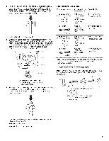
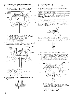
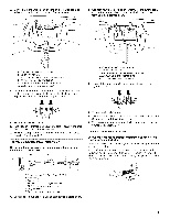
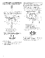
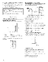
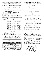
When connecting to the terminal block, place the hooked end of the wire under the screw of the terminal block (hook facing right), squeeze hooked end together and tighten screw, as shown. 1= Loosen or remove center silver-colored terminal block screw. 2. Place the hooked end of the neutral wire (white or center wire) of direct wire cable under the center screw of terminal block (hook facing right). Squeeze hooked end together. Tighten screw. Optional 3-wire connection Use for direct wire or power supply cord where local codes do not permit connecting cabinet-ground conductor to neutral wire. 1. Remove center silver-colored terminal block screw. 2. Remove neutral ground wire from external ground conductor screw. Connect neutral ground wire and the neutral wire (white or center wire) of power supply cord/cable under center, silver-colored terminal block screw. Tighten screw. D E A. External ground conductor screw B. Neutral ground wire C. Center silver-colored terminal block screw D. Neutral wire (white or center wire) E. _" (1.9 cm) UL listed strain relief 3= Place the hooked ends of the other direct wire cable wires under the outer terminal block screws (hooks facing right). Squeeze hooked ends together. Tighten screws. !! !! 4. Tighten strain relief screw. 5. Insert tab of terminal block cover into slot of dryer rear panel. Secure cover with hold-down screw. 6. You have completed your electrical connection. Now go to "Venting Requirements." A. External ground conductor screw B. Neutral ground wire C. Center silver-colored terminal block screw D. Neutral wire (white or center wire) E. _" (1.9 cm) UL listed strain relief F Grounding path determined by a qualified electrician 3= Connect the other wires to outer terminal block screws. Tighten screws. !! !! 4. Tighten strain relief screws. 5. Insert tab of terminal block cover into slot of dryer rear panel. Secure cover with hold-down screw. 6. Connect a separate copper ground wire from the external ground conductor screw to an adequate ground. 12
-
 1
1 -
2
-
3
-
4
-
5
-
6
-
 7
7 -
 8
8 -
 9
9 -
 10
10 -
 11
11 -
 12
12 -
 13
13 -
 14
14 -
 15
15 -
 16
16 -
 17
17 -
18
-
19
-
20
-
21
-
22
-
23
-
24
-
25
-
26
-
27
-
28
-
29
-
30
-
31
-
32
-
33
-
34
-
35
-
36
-
37
-
38
-
39
-
40
-
41
-
42
-
43
-
44
-
45
-
46
-
47
-
48
-
49
-
50
-
51
-
52
-
53
-
54
-
55
-
56
 |
 |
