Yamaha AVS-700 AVS-700 OWNERS MANUAL - Page 11
System, Connection, Diagram, a000riooTo, 0°0;0
 |
View all Yamaha AVS-700 manuals
Add to My Manuals
Save this manual to your list of manuals |
Page 11 highlights
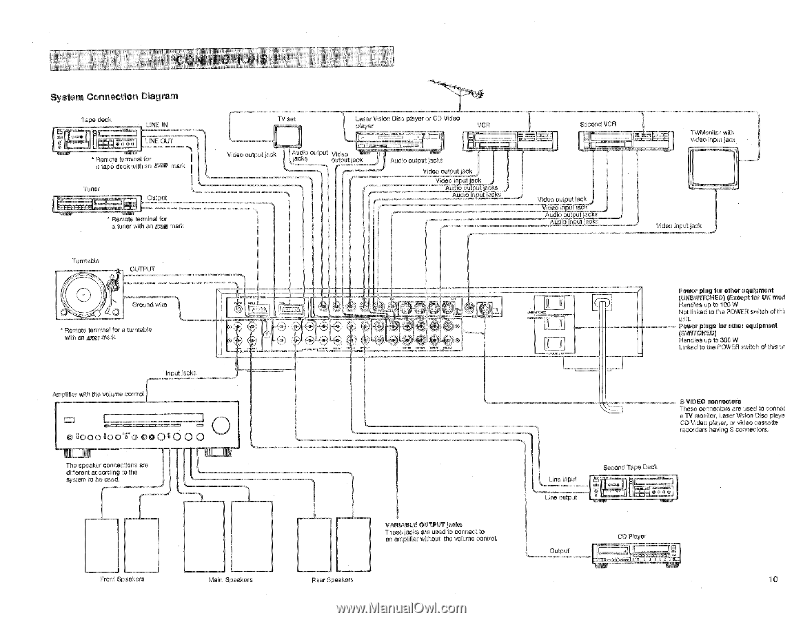
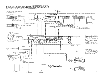
, CONNECTI9NS System Connection Diagram 5 gam a MAIM Tape deck LINE IN r i= imnrt LINE OUT * Remota terminal for a tape deck with an !RID mark Tuner Output MEM/ • Remote terminal for e. tuner with an Egge mark TV set Laser Vision Disc player or CD Video player VCR Video output jack Audio outpu jacks Video output jack 1 Audio output jacks Video output jackj Video input jack AuZio oulpplacks. , Audio input 1acWts Second VCR Video output jack Vidueooinout s • • sut ura16rac s Aucito input jacks TV/Monitor with video input jack i Video input jack Turntable OUTPUT Ground wire • Remote terminal for a turntable with an sap marl. Amplifier with the volume control Input jacks © a000riooTo 0°0;0 0 '0o The speaker con iections are different according to the system to be used. I 1 Froni Speakers Main Speakers Ll QtG e 01.01•• WRY. WO t/OPVIMMILI 1" Power plug for other equipment (UNSWITCHED) (Except for UK mod Handles up to 100 W Not linked to the POWER switch of thit unit. Power plugs for other equipment (SWITCHED) Hancres up to 300 W Linked to the POWER switch of this ur Rear Speakers Th VARIABLE OUTPUT jacks These jacks are used to connect to an amplifier without the volume control. S VIDEO connectors These connectors are used to connec a 1V monitor. Laser Vision Disc playa CD Video player, or video cassette recorders having S connectors. Line Input Line output Second Tape Deck t imisi oLircg•...i L OutputCDPlayer 7 2412_71-Tril; El= 10
-
 1
1 -
2
-
3
-
4
-
5
-
 6
6 -
 7
7 -
 8
8 -
 9
9 -
 10
10 -
 11
11 -
 12
12 -
 13
13 -
 14
14 -
 15
15 -
 16
16
 |
 |