Yamaha AVS-700 AVS-700 OWNERS MANUAL - Page 14
Basic, Operations
 |
View all Yamaha AVS-700 manuals
Add to My Manuals
Save this manual to your list of manuals |
Page 14 highlights
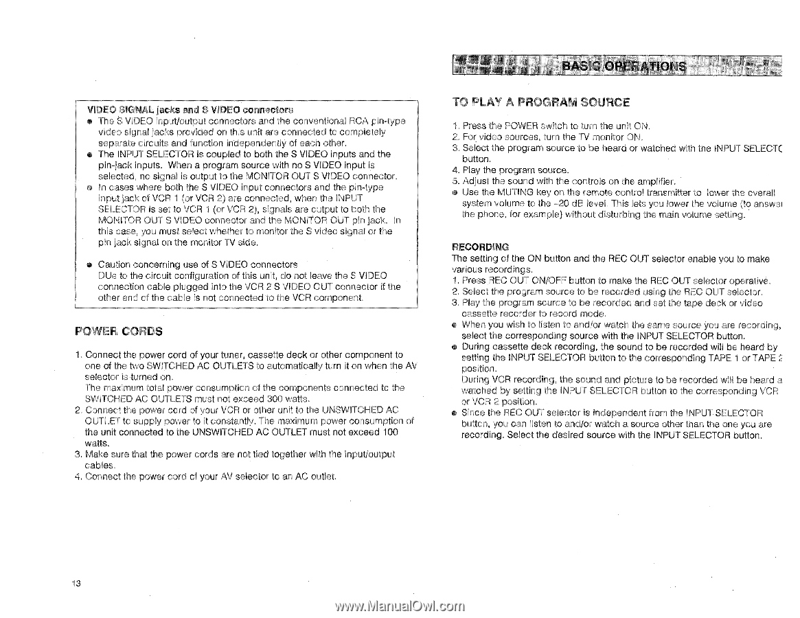
VIDEO SIGNAL jacks and S VIDEO connectors • The S VIDEO input/output connectors and the conventional RCA pin-type video signal jacks provided on this unit are connected to completely separate circuits and function independently of each other. • The INPUT SELECTOR is coupled to both the S VIDEO inputs and the pin-jack inputs. When a program source with no S VIDEO input is selected, no signal is output to the MONITOR OUT S VIDEO connector. • In cases where both the S VIDEO input connectors and the pin-type input jack of VCR 1 (or VCR 2) are connected, when the INPUT SELECTOR is set to VCR 1 (or VCR 2), signals are output to both the MONITOR OUT S VIDEO connector and the MONITOR OUT pin jack. In this case, you must select whether to monitor the S video signal or the pin jack signal on the monitor TV side. • Caution concerning use of S VIDEO connectors DUe to the circuit configuration of this unit, do not leave the S VIDEO connection cable plugged into the VCR 2 S VIDEO OUT connector if the other end of the cable is not connected to the VCR component. POWER CORDS 1. Connect the power cord of your tuner, cassette deck or other component to one of the two SWITCHED AC OUTLETS to automatically turn it on when the AV selector is turned on. The maximum total power consumption of the components connected to the SWITCHED AC OUTLETS must not exceed 300 watts. 2. Connect the power cord of your VCR or other unit to the UNSWITCHED AC OUTLET to supply power to it constantly. The maximum power consumption of the unit connected to the UNSWITCHED AC OUTLET must not exceed 100 watts. 3. Make sure that the power cords are not tied together with the input/output cables. 4. Connect the power cord of your AV selector to an AC outlet. BASIC OPERATIONS TO PLAY A PROGRAM SOURCE 1. Press the POWER switch to turn the unit ON. 2. For video sources, turn the TV monitor ON. 3. Select the program source to be heard or watched with the INPUT SELECT( button. 4. Play the program source. 5. Adjust the sound with the controls on the amplifier. • Use the MUTING key on the remote control transmitter to lower the overall system volume to the -20 dB level. This lets you lower the volume (to answer the phone, for example) without disturbing the main volume setting. RECORDING The setting of the ON button and the REC OUT selector enable you to make various recordings. 1. Press REC OUT ON/OFF button to make the REC OUT selector operative. 2. Select the program source to be recorded using the REC OUT selector. 3. Play the program source to be recorded and set the tape deck or video cassette recorder to record mode. • When you wish to listen to and/or watch the same source you are recording, select the corresponding source with the INPUT SELECTOR button. • During cassette deck recording, the sound to be recorded will be heard by setting the INPUT SELECTOR button to the corresponding TAPE 1 or TAPE 2 position. During VCR recording, the sound and picture to be recorded will be heard a watched by setting the INPUT SELECTOR button to the corresponding VCR or VCR 2 position. • Since the REC OUT selector is independent from the INPUT SELECTOR button, you can listen to and/or watch a source other than the one you are recording. Select the desired source with the INPUT SELECTOR button. 13
-
 1
1 -
2
-
3
-
4
-
5
-
6
-
7
-
8
-
 9
9 -
 10
10 -
 11
11 -
 12
12 -
 13
13 -
 14
14 -
 15
15 -
 16
16
 |
 |