Yamaha AVS-700 AVS-700 OWNERS MANUAL - Page 8
Yamaha AVS-700 Manual
 |
View all Yamaha AVS-700 manuals
Add to My Manuals
Save this manual to your list of manuals |
Page 8 highlights
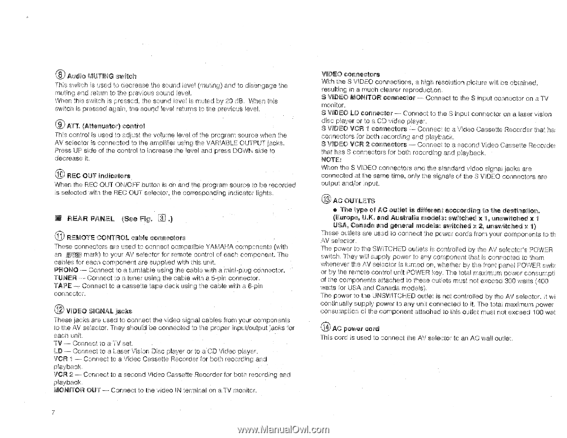
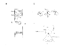
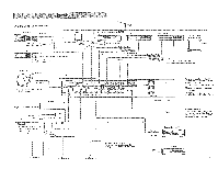
Audio MUTING switch This switch is used to decrease the sound level (muting) and to disengage the muting aid return to the previous sound level. When this switch is pressed, the sound level is muted by 20 dB. When this switch is pressed again, the sound level returns to the previous level. 0 ATT. (Attenuator) control This control is used to adjust the volume level of the program source when the AV selector is connected to the amplifier using the VARIABLE OUTPUT jacks. Press UP side of the control to increase the level and press DOWN side to decrease it. 10 REC OUT indicators When the REC OUT ON/OFF button is on and the program source to be recorded is selected with the REC OUT selector, the corresponding indicator lights. IM REAR PANEL (See Fig. Ell 0 REMOTE CONTROL cable connectors These connectors are used to connect compatible YAMAHA components (with an m$ Egi mark) to your AV selector for remote control of each component. The cables for each component are supplied with this unit. PHONO -- Connect to a turntable using the cable with a mini-plug connector. TUNER - Connect to a tuner using the cable with a 5-pin connector. TAPE - Connect to a cassette tape deck using the cable with a 6-pin connector. VIDEO SIGNAL jacks These jacks are used to connect the video signal cables from your components to the AV selector. They should be connected to the proper input/output jacks for each unit. TV - Connect to a TV set. LD - Connect to a Laser Vision Disc player or to a CD Video player. VCR 1 - Connect to a Video Cassette Recorder for both recording and playback. VCR 2 - Connect to a second Video Cassette Recorder for both recording and playback. MONITOR OUT - Connect to the video IN terminal on a TV monitor. 7 VIDEO connectors With the S VIDEO connections, a high resolution picture will be obtained, resulting in a much clearer reproduction. S VIDEO MONITOR connector - Connect to the S input connector on a TV monitor. S VIDEO LD connector - Connect to the S input connector on a laser vision disc player or to a CD video player. S VIDEO VCR 1 connectors - Connect to a Video Cassette Recorder that ha connectors for both recording and playback. S VIDEO VCR 2 connectors - Connect to a second Video Cassette Recorder that has S connectors for both recording and playback. NOTE: When the S VIDEO connectors and the standard video signal jacks are connected at the same time, only the signals of the S VIDEO connectors are output and/or input. e AC OUTLETS a The type of AC outlet is different acccording to the destination. (Europe, U.K. and Australia models: switched x 1, unswitched x 1 USA, Canada and general models: switched x 2, unswitched x 1) These outlets are used to connect the power cords from your components to th AV selector. The power to the SWITCHED outlets is controlled by the AV selector's POWER switch. They will supply power to any component that is connected to them whenever the AV selector is turned on, whether by the front panel POWER swit( or by the remote control unit POWER key. The total maximum power consumpti of the components attached to these outlets must not exceed 300 watts (400 watts for USA and Canada models). The power to the UNSWITCHED outlet is not controlled by the AV selector. It wi continually supply power to any unit connected to it. The total maximum power consumption of the component attached to this outlet must not exceed 100 wat 0 AC power cord This cord is used to connect the AV selector to an AC wall outlet.
-
 1
1 -
2
-
 3
3 -
 4
4 -
 5
5 -
 6
6 -
 7
7 -
 8
8 -
 9
9 -
 10
10 -
 11
11 -
 12
12 -
 13
13 -
14
-
15
-
16
 |
 |