Yamaha AVS-700 AVS-700 OWNERS MANUAL - Page 13
VIDEO, COMPONENTS, Connect, video, output, SIGNAL, panel, connect, audio, jacks, AUDIO, jacks.
 |
View all Yamaha AVS-700 manuals
Add to My Manuals
Save this manual to your list of manuals |
Page 13 highlights
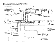
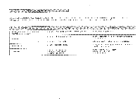
VIDEO COMPONENTS ® TV SET Connect the video output jack from the TV set to the TV VIDEO SIGNAL jack on the rear panel of this unit and connect the audio output jacks from the TV set to the TV AUDIO SIGNAL jacks. ■ LASER VISION DISC PLAYER/CDV PLAYER Connect the video output jack from the laser vision disc player/CD video player to the LD/CDV VIDEO SIGNAL jack and connect the audio output jacks from the laser vision disc player/CD video player to the LD/CDV AUDIO SIGNAL jacks. When using the S connector • When a laser vision disc player or a CD video player that has an S video connector is used, connect S VIDEO LD/CDV connector. With the S video connections, a high resolution picture will be obtained, resulting in much clearer reproduction. ■ VCR (Video Cassette Recorder) Connect the video jacks of the VCR to the VCR 1 VIDEO SIGNAL jacks, and connect the video jacks of a second VCR to the VCR 2 VIDEO SIGNAL jacks on the rear panel of this unit. The video playback (VIDEO OUT) jack of the VCR goes to the IN jack, and the video record (VIDEO IN) jack goes to the OUT jack. Connect the audio output jacks of the VCR to the VCR 1 AUDIO SIGNAL jacks, and connect the audio output jacks of a second VCR to the VCR 2 AUDIO SIGNAL jacks. The audio playback (AUDIO LINE OUT) jacks of the VCR go to the TAPE PB jacks, and the audio record (AUDIO LINE IN) jacks go to the REC OUT jacks. When using the S connector • When a VCR that has S connectors is used, connect the S VIDEO connectors. With the S VIDEO connections, a high resolution picture will be obtained, resulting in a much clearer reproduction. Connect the S output connector of the VCR to the S VIDEO IN connector in the VCR 2 section on the rear panel of this unit, and connect the S input connector of the VCR to the S VIDEO OUT connector. Connect the S output connector of the VCR only for playback to the S VIDEO IN connector in the VCR 1 section on the rear panel of this unit. • Keep the VCR IN and OUT jacks, and TAPE PB and REC OUT jacks connected between the VCR and this unit. If the second VCR has S connectors, connect the S output and input connectors to the S VIDEO IN and OUT connectors in the VCR 2 section on the rear panel of this unit in the same way. IN TV MONITOR Connect the video jack from the TV monitor to the MONITOR OUT jack on the rear panel of this unit. Note that audio connections to the monitor are not necessary, as the audio portion of the signal is sent to your speakers through the amplifier. When using the S connector • When a monitor that has an S video connector is used, connect S VIDEO MONITOR OUT connector. With the S VIDEO connections, a high resolution picture will be obtained, resulting in a much clearer reproduction. Mi OTHER VIDEO SOURCE If necessary, you can connect a third video input source, such as a video camera, to the AUX jacks on the front panel of this unit. To obtain a high resolution picture, connect S input connector on a video camera, etc. to the S VIDEO connector. 12
-
 1
1 -
2
-
3
-
4
-
5
-
6
-
7
-
 8
8 -
 9
9 -
 10
10 -
 11
11 -
 12
12 -
 13
13 -
 14
14 -
 15
15 -
 16
16
 |
 |