Yamaha AVS-700 AVS-700 OWNERS MANUAL - Page 12
Connections, Component, Amplifier
 |
View all Yamaha AVS-700 manuals
Add to My Manuals
Save this manual to your list of manuals |
Page 12 highlights
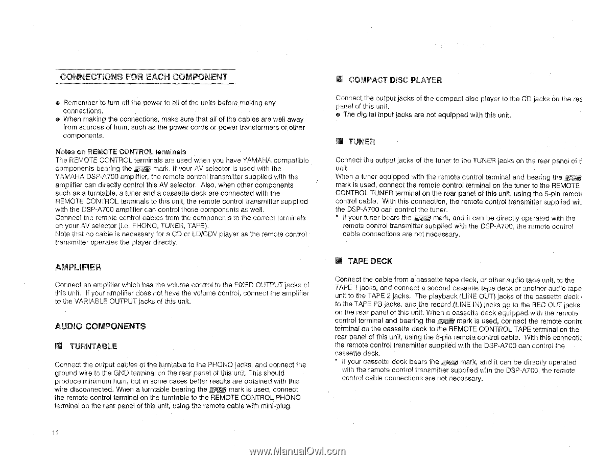
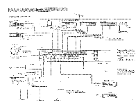
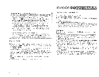
CONNECTIONS FOR EACH COMPONENT • Remember to turn off the power to all of the units before making any connections. • When making the connections, make sure that all of the cables are well away from sources of hum, such as the power cords or power transformers of other components. Notes on REMOTE CONTROL terminals The REMOTE CONTROL terminals are used when you have YAMAHA compatible components bearing the ma mark. If your AV selector is used with the YAMAHA DSP-A700 amplifier, the remote control transmitter supplied with the amplifier can directly control this AV selector. Also, when other components such as a turntable, a tuner and a cassette deck are connected with the REMOTE CONTROL terminals to this unit, the remote control transmitter supplied with the DSP-A700 amplifier can control those components as well. Connect tne remote control cables from the components to the correct terminals on your AV selector (i.e. PHONO, TUNER, TAPE). Note that no cable is necessary for a CD or LD/CDV player as the remote control transmitter operates the player directly. AMPLIFIER Connect an amplifier which has the volume control to the FIXED OUTPUT jacks of this unit. If your amplifier does not have the volume control, connect the amplifier to the VARIABLE OUTPUT jacks of this unit. AUDIO COMPONENTS I TURNTABLE Connect the output cables of the turntable to the PHONO jacks, and connect the ground wire to the GND terminal on the rear panel of this unit. This should produce minimum hum, but in some cases better results are obtained with this wire disconnected. When a turntable bearing the mark is used, connect the remote control terminal on the turntable to the REMOTE CONTROL PHONO terminal on the rear panel of this unit, using the remote cable with mini-plug. 11 • COMPACT DISC PLAYER Connect the output jacks of the compact disc player to the CD jacks on the re8 panel of this unit. • The digital input jacks are not equipped with this unit. Ed TUNER Connect the output jacks of the tuner to the TUNER jacks on the rear panel of ti unit. When a tuner equipped with the remote control terminal and bearing the =Eg) mark is used, connect the remote control terminal on the tuner to the REMOTE CONTROL TUNER terminal on the rear panel of this unit, using the 5-pin remote control cable. With this connection, the remote control transmitter supplied wit] the DSP-A700 can control the tuner. * If your tuner bears the grp,kri mark, and it can be directly operated with the remote control transmitter supplied with the DSP-A700, the remote control cable connections are not necessary. • TAPE DECK Connect the cable from a cassette tape deck, or other audio tape unit, to the TAPE 1 jacks, and connect a second cassette tape deck or another audio tape unit to the TAPE 2 jacks. The playback (LINE OUT) jacks of the cassette deck to the TAPE PB jacks, and the record (LINE IN) jacks go to the REC OUT jacks on the rear panel of this unit. When a cassette deck equipped with the remote control terminal and bearing the me mark is used, connect the remote contr.( terminal on the cassette deck to the REMOTE CONTROL TAPE terminal on the rear panel of this unit, using the 6-pin remote control cable. With this connectic the remote control transmitter supplied with the DSP-A700 can control the cassette deck. * If your cassette deck bears the MN mark, and it can be directly operated with the remote control transmitter supplied with the DSP-A700, the remote control cable connections are not necessary.
-
 1
1 -
2
-
3
-
4
-
5
-
6
-
 7
7 -
 8
8 -
 9
9 -
 10
10 -
 11
11 -
 12
12 -
 13
13 -
 14
14 -
 15
15 -
 16
16
 |
 |