Yamaha HTR-5540 Owners Manual
Yamaha HTR-5540 Manual
 |
View all Yamaha HTR-5540 manuals
Add to My Manuals
Save this manual to your list of manuals |
Yamaha HTR-5540 manual content summary:
- Yamaha HTR-5540 | Owners Manual - Page 1
U HTR-5540 AV Receiver OWNER'S MANUAL - Yamaha HTR-5540 | Owners Manual - Page 2
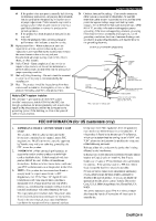
SERVICEABLE PARTS INSIDE. REFER SERVICING TO QUALIFIED SERVICE home, consult your product dealer or local power company. For products intended to operate from battery power, or other sources, refer to the operating instructions When installing an outside antenna system, extreme care should be taken - Yamaha HTR-5540 | Owners Manual - Page 3
instructions. Adjust only those controls that are covered by the operating instructions as an improper adjustment of other controls may result in damage and will often require extensive work POWER SERVICE GROUNDING ELECTRODE SYSTEM (NEC ART 250. PART H) NEC - NATIONAL ELECTRICAL CODE FCC - Yamaha HTR-5540 | Owners Manual - Page 4
YAMAHA service personnel when any service is needed. The cabinet should never be opened for any reasons. When not planning to use this unit for long periods of time (i.e. vacation), disconnect the AC power plug from the wall outlet. Be sure to read the "TROUBLESHOOTING this Owner's Manual in - Yamaha HTR-5540 | Owners Manual - Page 5
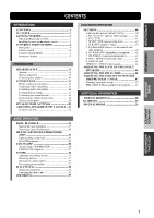
...4 Remote control ...6 Using the remote control ...7 Front panel display ...8 PREPARATION PREPARATION SPEAKER SETUP ...9 Speakers ...9 Speaker placement ...9 Connecting the speakers ...10 CONNECTIONS ...13 Before connecting components ...13 Connecting video components ...14 Connecting audio - Yamaha HTR-5540 | Owners Manual - Page 6
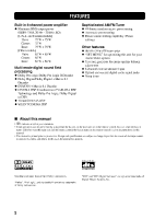
Other features N 96-kHz/24-bit D/A converter N "SET MENU" for optimizing this unit for your Audio/Video system N Test tone generator for easier speaker balance adjustment N 6-channel external decoder input N Optical and coaxial digital audio signal jacks N Sleep timer Multi-mode digital sound field - Yamaha HTR-5540 | Owners Manual - Page 7
THEATER - 2 q / DTS SUR. MATRIX 6.1 SELECT LEVEL SET MENU - DSP TEST + BASIC OPERATION STEREO EFFECT MUTE A/V cable (U.S.A., Canada and Australia models) (Europe, U.K., Australia and Singapore models) VOLUME Installing batteries in the remote control 3 Press the part and slide off the - Yamaha HTR-5540 | Owners Manual - Page 8
the input source you want to listen to or watch. 6 VOLUME Controls the output level of all audio channels. This does not affect the OUT (REC) level. 2 Remote control sensor Receives signals from the remote control. 7 6CH INPUT Selects the audio source connected to the 6CH INPUT jacks. This - Yamaha HTR-5540 | Owners Manual - Page 9
CONTROLS AND FUNCTIONS 8 SILENT (PHONES jack) Allows you enjoy DSP effect for private listening with headphones. When you connect headphones, no signals are output to the speakers. 9 STEREO/EFFECT Switches between normal stereo and DSP effect reproduction. When STEREO is selected, 2-channel manual - Yamaha HTR-5540 | Owners Manual - Page 10
to adjust the speaker levels. ENTERTAINMENT TV SPORTS MONO MOVIE 5 MOVIE 1 - THEATER - 2 q / DTS SUR. 9 MUTE Mutes the sound. Press again to restore the audio output to the previous volume level. MATRIX 6.1 0 VOLUME h/g SELECT Increases or decreases the volume level. LEVEL SET MENU q 6CH - Yamaha HTR-5540 | Owners Manual - Page 11
TV SPORTS MONO MOVIE MOVIE 1 - THEATER - 2 q / DTS SUR. MATRIX 6.1 SELECT LEVEL SET MENU - DSP + TEST STEREO EFFECT MUTE VOLUME The remote control transmits a directional infrared beam. Be sure to aim the remote control directly at the remote control sensor on the main unit during - Yamaha HTR-5540 | Owners Manual - Page 12
on. t Input channel indicator Indicates the channel components of input signals being received. 7 Headphones indicator Lights up when headphones are connected. 8 DSP program indicators The name of the selected DSP program lights up when the ENTERTAINMENT, MOVIE THEATER 1, MOVIE THEATER 2 or V/DTS - Yamaha HTR-5540 | Owners Manual - Page 13
the LFE (low-frequency effect) channel with high fidelity when playing back Dolby Digital or DTS signals. The YAMAHA Active Servo Processing Subwoofer System is ideal for natural and lively bass reproduction. ADVANCED OPERATION I Rear speakers Place these speakers behind your listening position - Yamaha HTR-5540 | Owners Manual - Page 14
impedance shown on the rear panel of this unit. • Do not let the bare speaker wires touch each other or any metal part of this unit. This could damage this unit and/ or the speakers. If necessary, use the SET MENU to change the speaker mode settings according to the number and size of the - Yamaha HTR-5540 | Owners Manual - Page 15
MONITOR OUT VIDEO AUDIO OUTPUT 4 Subwoofer system 5 Right 6 Left Rear speaker 3 2 1 4 5 6 The diagram shows the speaker layout in the listening room. I SUBWOOFER jack When using a subwoofer with built-in amplifier, including the YAMAHA Active Servo Processing Subwoofer System, connect - Yamaha HTR-5540 | Owners Manual - Page 16
the switch position (left or right) according to the impedance of the speakers in your system. Be sure to move this switch only when this unit is in the standby mode. SPEAKERS Switch position R Speaker Impedance level R MAIN L REAR L (SURROUND) CENTER Main + - + MAIN CENTER REAR : 4ΩMIN - Yamaha HTR-5540 | Owners Manual - Page 17
instructions for each component to be connected to this unit. • When you connect other YAMAHA audio SPEAKERS DIGITAL INPUT COAXIAL CD SURROUND MAIN 6CH INPUT AUDIO VIDEO R L VIDEO L SUB WOOFER MONITOR OUT VIDEO AUDIO OUTPUT SUBWOOFER OUTPUT jack (page 11) Audio component jacks (page 16) - Yamaha HTR-5540 | Owners Manual - Page 18
as a game console or camcorder. I Connecting a VCR or DVR (digital video recorder) Connect the audio signal input jacks on your video component to the AUDIO OUT jacks and connect the video signal input jack on the video component to the VIDEO OUT jack on this unit for picture recording. Connect the - Yamaha HTR-5540 | Owners Manual - Page 19
R VCR Another video component AUDIO OUTPUT TV/digital TV/ cable TV AUDIO INPUT L R AUDIO OUTPUT L R V VIDEO VIDEO OUTPUT INPUT V AUDIO OUTPUT L R V VIDEO OUTPUT V VIDEO OUTPUT PREPARATION DIGITAL INPUT COAXIAL CD SURROUND MAIN 6CH INPUT AUDIO VIDEO R L VIDEO V-AUX TUNER AM - Yamaha HTR-5540 | Owners Manual - Page 20
this unit. If the power is off, this unit may distort the sound from other components. DIGITAL INPUT 6CH INPUT MAIN AUDIO VIDEO CD player COAXIAL OUTPUT C COAXIAL CD R L VIDEO SURROUND V-AUX TUNER AM ANT SUB WOOFER CENTER IN GND OPTICAL VCR OUT 75Ω UNBAL. IN (PLAY) MD /CD-R OUT (REC - Yamaha HTR-5540 | Owners Manual - Page 21
INTRODUCTION 1 Set up the AM loop antenna, then connect it. PREPARATION 2 EO VIDEO Press and hold the tab to insert the AM loop antenna lead wires into the may improve the quality. Consult the nearest authorized YAMAHA dealer or service center about the outdoor antennas. FREQUENCY STEP switch - Yamaha HTR-5540 | Owners Manual - Page 22
and SUBWOOFER) for discrete multi-channel input from an external decoder, sound processor, or pre-amplifier. INPUT as the input source, settings of "1 SPEAKER SET" on the SET MENU do not apply (except for "1E MAIN Lv unit. The power to the AC OUTLETS is controlled by this unit's STANDBY/ON (or POWER). - Yamaha HTR-5540 | Owners Manual - Page 23
power of this unit. INTRODUCTION 1 INPUT VOLUME 6CH INPUT INPUT M0DE NATURAL SOUND AV RECEIVER STANDBY /ON BASS SILENT STEREO PROGRAM MEMORY panel Remote control The level of the main volume, and then the current DSP program name appear on the front panel display. 2 Turn on the video - Yamaha HTR-5540 | Owners Manual - Page 24
MODE SETTINGS This unit has 5 SPEAKER SET items on the SET MENU that you must set according to the number of speakers in your configuration and their size. The following table summarizes these SPEAKER SET items, and shows the initial settings as well as other possible settings. If the initial - Yamaha HTR-5540 | Owners Manual - Page 25
. The adjustment of each speaker output level should be made at your listening position using the remote control. - VOLUME BASS TREBLE Remote control + - + BASIC OPERATION Front panel 2 INPUT VOLUME 6CH INPUT LEFT RIGHT INPUT M0DE NATURAL SOUND AV RECEIVER STANDBY /ON CENTER BASS - Yamaha HTR-5540 | Owners Manual - Page 26
level of the main speakers, use VOLUME knob (or VOLUME h/g on the remote control). 4 When adjustment is complete, press TEST to stop the test tone. TEST Notes • If "1A CENTER" on the SET MENU is set to NON and the center speaker is not connected, the center channel sound is automatically output - Yamaha HTR-5540 | Owners Manual - Page 27
input to which the video source component is connected before selecting audio source. Press 6CH INPUT until "6CH INPUT" appears on the front panel display. 6CH INPUT ADVANCED OPERATION 5 VOLUME 6CH INPUT or Front panel Remote control 1 Press STANDBY/ON (POWER on the remote control) to turn on - Yamaha HTR-5540 | Owners Manual - Page 28
bar graph. If desired, use BASS and TREBLE. These controls only effect the sound from the main speakers. VOLUME I BGV (background video) function The BGV function allows you to enjoy video images from a video source together with sounds from an audio source. For example, you can enjoy listening to - Yamaha HTR-5540 | Owners Manual - Page 29
the subwoofer depending on the SPEAKER MODE settings on the SET MENU.) Therefore, the level of the effect speakers cannot be adjusted while listening to such a source. INTRODUCTION 1 Press INPUT MODE (the input selector button that you have pressed to select the input source on the remote control - Yamaha HTR-5540 | Owners Manual - Page 30
set to NON, the center channel sound is output from the main speakers.) PROGRAM HALL JAZZ CLUB ROCK CONCERT ENTERTAINMENT TV SPORTS MONO MOVIE 1,2 MOVIE 1 - THEATER - 2 q / DTS SUR. MATRIX 6.1 SELECT EVE SET MENU 1 Press one of the DSP program buttons on the remote control to select the - Yamaha HTR-5540 | Owners Manual - Page 31
channels by selecting PRO LOGIC in program No. 9. INPUT VOLUME 6CH INPUT 3 Press SELECT repeatedly to select the decoder; PRO LOGIC or PRO LOGIC . PROGRAM HALL JAZZ CLUB ROCK CONCERT INTRODUCTION ENTERTAINMENT TV SPORTS MONO MOVIE INPUT M0DE NATURAL SOUND AV RECEIVER MOVIE 1 - THEATER - Yamaha HTR-5540 | Owners Manual - Page 32
the main speakers. • The volume may be greatly reduced when you turn off the sound effects or if you set "4 D. RANGE" on the SET MENU to MIN. In this case turn on the sound effect. • The sound of LFE channel will be directed to the main left and right or the subwoofer (or both) channels depending - Yamaha HTR-5540 | Owners Manual - Page 33
your listening room. The traditional stereo system that uses only two speakers is not capable of recreating a realistic sound field. YAMAHA's DSP requires three effect speakers to recreate sound fields based on the measured sound field data. The processor controls the strength and delay time of the - Yamaha HTR-5540 | Owners Manual - Page 34
your audio room. In CINEMA-DSP sound field programs, YAMAHA's exclusive DSP processing is added to the Main left and right, and Center channels, 6.1 decoder for adding a rear center channel (the rear center channel is outputted from virtual rear center speaker). You can select CINEMA-DSP programs to - Yamaha HTR-5540 | Owners Manual - Page 35
channel soundtracks do. The built-in Dolby Digital or DTS decoder brings the professional-quality sound designed for movie theaters into your home. With this unit's MOVIE THEATER center DSP sound field created from the virtual rear center speaker. BASIC OPERATION I Dolby Pro Logic + DSP sound field - Yamaha HTR-5540 | Owners Manual - Page 36
for Each Input Format Input 2 channel Stereo No. 7 Program MOVIE THEATER 1 70 mm Spectacle 70 mm Sci-Fi 8 MOVIE THEATER 2 70 mm Adventure 70 mm General MATRIX 6.1 on the remote control can be used to play Dolby Digital or DTS 5.1 channel sources with the virtual rear center speaker. In this case the - Yamaha HTR-5540 | Owners Manual - Page 37
ideally simulates the multi-surround speaker systems of the 35-mm film theaters. Dolby Pro Logic decoding, THEATER 2 Adventure General BASIC OPERATION 9 Enhanced Mode ADVANCED OPERATION I For audio-video sources: No. 4 to 6 No. 4 Program ENTERTAINMENT/ Game ENTERTAINMENT/ Concert Video - Yamaha HTR-5540 | Owners Manual - Page 38
CD-R TUNER TUNED I Automatic tuning 1 INPUT VOLUME 6CH INPUT A AM 144O INPUT M0DE NATURAL SOUND AV RECEIVER When tuned in to a station, the select is weak, you must tune in to it manually. 1 1 Press INPUT l / h (TUNER on the remote control) to select TUNER as the input source. Select TUNER - Yamaha HTR-5540 | Owners Manual - Page 39
selecting the preset station number (see page 37). INPUT VOLUME 6CH INPUT Notes • Any stored station data existing manually in the monaural mode, and store it by following the procedure in "Manually presetting stations" on page 36. INTRODUCTION PREPARATION INPUT M0DE NATURAL SOUND AV RECEIVER - Yamaha HTR-5540 | Owners Manual - Page 40
(8 stations x 5 groups) manually. INPUT VOLUME 6CH INPUT 4 INPUT M0DE NATURAL SOUND AV RECEIVER Press PRESET/TUNING l / instructions. VCR V-AUX D-TV/CBL DVD MD/CD-R TUNER TUNED 5 CD VOLUME A AM 63O kHz L R When tuned in to a station, the front panel display shows the frequency of received - Yamaha HTR-5540 | Owners Manual - Page 41
"A5". INPUT VOLUME 6CH INPUT INTRODUCTION INPUT M0DE NATURAL SOUND AV RECEIVER INPUT M0DE NATURAL SOUND AV RECEIVER STANDBY /ON STANDBY TUNING 2 MOVIE 1 - THEATER - 2 q / DTS SUR. MATRIX 6.1 SELECT BASIC OPERATION 1 Press A/B/C/D/E (A/B/C/D/E on the remote control) to select the preset - Yamaha HTR-5540 | Owners Manual - Page 42
instructions of the timer. y • The sleep timer setting can also be canceled by setting this unit in the standby mode by using POWER on the remote control below. SLEEP VCR V-AUX D-TV/CBL DVD MD/CD-R TUNER CD SLEEP VOLUME DSP PCM SLEEP 12Omin L R 3 The "SLEEP" indicator lights up on - Yamaha HTR-5540 | Owners Manual - Page 43
1 INPUT M0DE 2 INPUT VOLUME 6CH INPUT NATURAL SOUND AV RECEIVER STANDBY /ON PREPARATION BASS SILENT Remote control I Timer playback/recording ADDITIONAL INFORMATION This unit can perform playback or recording with an external timer (not supplied). Refer to the operating instructions - Yamaha HTR-5540 | Owners Manual - Page 44
MENU Adjustment should be made with the remote control. PROGRAM HALL JAZZ CLUB ROCK CONCERT y • You can adjust the items on the SET MENU while playing a source. Items 1 SPEAKER MAX 0 dB for L/R MOVIE 1 - THEATER - 2 q / DTS SUR. MATRIX 6.1 SELECT LEVEL SET MENU 2,5 1 3,4 - DSP TEST + 2 - Yamaha HTR-5540 | Owners Manual - Page 45
THEATER - 2 q / DTS SUR. MATRIX 6.1 I 1A CENTER (center speaker mode) By adding a center speaker to your speaker large center speaker. The entire range of the center channel signal is directed to the center speaker. SML Select this if you have a small center speaker. The lowfrequency - Yamaha HTR-5540 | Owners Manual - Page 46
MENU I 1C REAR LR (rear speaker mode) Choices: LRG (large), SML (small), NON (none) LRG Select this if you have large rear left and right speakers or if a rear subwoofer is connected to the rear speakers. The entire range of the rear channel signal is directed to the rear left and right speakers - Yamaha HTR-5540 | Owners Manual - Page 47
of the center channel sounds. This feature works when there is sound output from the center speaker, with a source like Dolby Digital or DTS, etc. Ideally, the center speaker should be the same distance from the main listening position as the left and right speakers. However, in most home situations - Yamaha HTR-5540 | Owners Manual - Page 48
front panel display. Control range: -4 to 0 Initial setting: 0 10 MEM. GUARD (memory guard) Use this feature to prevent accidental changes to settings on this unit. Choices: ON, OFF Select ON to protect the following features: • All SET MENU items • Center, rear speakers, and subwoofer levels • DSP - Yamaha HTR-5540 | Owners Manual - Page 49
Each time you press LEVEL, the selected speaker changes and appears on the front panel display as follows: center, rear right, rear left and subwoofer. LEVEL I For 5ch Stereo You can adjust the volume level for each channel in 5channel stereo mode. Control range: 0 to 100% • CT level (Center level - Yamaha HTR-5540 | Owners Manual - Page 50
15 5 5 5 20 5 5 5 15 5 Adjustment should be made with the remote control. PROGRAM HALL JAZZ CLUB ROCK CONCERT ENTERTAINMENT TV SPORTS MONO MOVIE 1 MOVIE 1 - THEATER - 2 q / DTS SUR. MATRIX 6.1 SELECT LEVEL SET MENU 1. 2. 3. 4. 2 - DSP TEST + STEREO EFFECT 3 (While playing a source - Yamaha HTR-5540 | Owners Manual - Page 51
the remote control. PROGRAM MENU 2 - DSP TEST + STEREO EFFECT I CT WIDTH (Center width) 3 Function: Adjusts the center image from all three front speakers to varying degrees. The larger the value, adjusts the center image towards the main left and right speakers. Control range: 0 (center channel - Yamaha HTR-5540 | Owners Manual - Page 52
instruction below does not help, set this unit to the standby mode, disconnect the power cord, and contact the nearest authorized YAMAHA dealer or service center. I General Problem standby mode. 12 Make sure all speaker wire connections on this unit and on all speakers are secure and that the wire - Yamaha HTR-5540 | Owners Manual - Page 53
is set to SWFR or MAIN when a 2-channel source is being played. The source does not contain low bass signals (90 Hz and below). Poor bass reproduction. "1D BASS" on the SET MENU is set to SWFR or BOTH and your system does not include a subwoofer. The speaker mode settings (main, center, or rear) on - Yamaha HTR-5540 | Owners Manual - Page 54
TROUBLESHOOTING Problem Cause Remedy Refer to page 10 - 16 A "humming" sound can be heard. The volume MENU to OFF. - - The internal microcomputer has been frozen by an external electric shock (such as lightning or excessive static electricity) or by a power supply with low voltage. Speaker - Yamaha HTR-5540 | Owners Manual - Page 55
connections and orient it for best reception. Use the manual tuning method. 17 34 17 AM There are continuous crackling Remote control ADDITIONAL INFORMATION Problem Cause Remedy Refer to page 7 The remote control does not work nor function properly. Wrong distance or angle. The remote control - Yamaha HTR-5540 | Owners Manual - Page 56
theater system so that you can enjoy the depth of sound and natural spatial representation of DTS digital surround in your home. This system produces practically distortion-free 6-channel sound (technically, a left, right and center channels, 2 rear channels, plus an LFE 0.1 channel as a subwoofer - Yamaha HTR-5540 | Owners Manual - Page 57
2-speaker system that does not include a center speaker. INTRODUCTION I PCM (Linear PCM) Linear PCM is a signal format under which an analog audio DVD audio. The PCM system uses a technique for sampling the size of the analog signal per very small unit of time. Standing for "pulse code modulation - Yamaha HTR-5540 | Owners Manual - Page 58
Network) Main L/R ...150 µV or less • Channel Separation (1 kHz/10 kHz) CD (5.1 kΩ terminated) to Main L/R ...60 dB/45 dB • Tone Control 10.0 kg (21.3 lbs) • Accessories ...Remote control Batteries 75-ohm/300-ohm antenna adapter [U.K. VIDEO SECTION • Video Signal Type ...NTSC or PAL • Composite Video - Yamaha HTR-5540 | Owners Manual - Page 59
HAMBURG, F.R. OF GERMANY ELECTRONIQUE FRANCE S.A. RUE AMBROISE CROIZAT BP70 CROISSY-BEAUBOURG 77312 MARNE-LA-VALLEE CEDEX02, FRANCE ELECTRONICS (UK) LTD. YAMAHA HOUSE, 200 RICKMANSWORTH ROAD WATFORD, HERTS WD1 7JS, ENGLAND SCANDINAVIA A.B. J A WETTERGRENS GATA 1, BOX 30053, 400 43 VÄSTRA FRÖLUNDA
-
 1
1 -
 2
2 -
 3
3 -
 4
4 -
 5
5 -
 6
6 -
 7
7 -
8
-
9
-
10
-
11
-
12
-
13
-
14
-
15
-
16
-
17
-
18
-
19
-
20
-
21
-
22
-
23
-
24
-
25
-
26
-
27
-
28
-
29
-
30
-
31
-
32
-
33
-
34
-
35
-
36
-
37
-
38
-
39
-
40
-
41
-
42
-
43
-
44
-
45
-
46
-
47
-
48
-
49
-
50
-
51
-
52
-
53
-
54
-
55
-
56
-
57
-
58
-
59
 |
 |

OWNER’S MANUAL
HTR-5540
U
AV Receiver