Yamaha HTR-5940 Owners Manual - Page 28
Connecting the power cable, AC OUTLETS SWITCHED - not turning on
 |
View all Yamaha HTR-5940 manuals
Add to My Manuals
Save this manual to your list of manuals |
Page 28 highlights
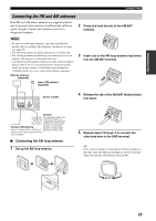
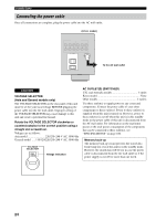
CONNECTIONS Connecting the power cable Once all connections are complete, plug the power cable into the AC wall outlet. (U.S.A. model) AC OUTLETS To the AC wall outlet CAUTION VOLTAGE SELECTOR (Asia and General models only) The VOLTAGE SELECTOR on the rear panel of this unit must be set for your local voltage BEFORE plugging the power cable into the AC wall outlet. Improper setting of the VOLTAGE SELECTOR may cause damage to this unit and create a potential fire hazard. Rotate the VOLTAGE SELECTOR clockwise or counterclockwise to the correct position using a straight slot screwdriver. Voltages are as follows: Asia model 220/230-240 V AC, 50/60 Hz General model .....110/120/220/230-240 V AC, 50/60 Hz VOLTAGE SELECTOR 230240V Voltage indication AC OUTLET(S) (SWITCHED) U.K. and Australia models 1 outlet Korea model None Other models 2 outlets Use these outlet(s) to supply power to any connected components. Connect the power cable of your other components to these outlet(s). Power to these outlet(s) is supplied when this unit is turned on. However, power to these outlet(s) is cut off when this unit is in the standby mode or the power cable of this unit is disconnected from the AC wall outlet. For information on the maximum power or the total power consumption of the components that can be connected to these outlet(s), see "SPECIFICATIONS" on page 100. Memory back-up The memory back-up circuit prevents the stored data from being lost even if this unit is in the standby mode. However, the stored data will be lost in case the power cable is disconnected from the AC wall outlet or if the power supply is cut off for more than one week. 24
-
 1
1 -
2
-
3
-
4
-
5
-
6
-
7
-
8
-
9
-
10
-
11
-
12
-
13
-
14
-
15
-
16
-
17
-
18
-
19
-
20
-
21
-
22
-
 23
23 -
 24
24 -
 25
25 -
 26
26 -
 27
27 -
 28
28 -
 29
29 -
 30
30 -
 31
31 -
 32
32 -
 33
33 -
34
-
35
-
36
-
37
-
38
-
39
-
40
-
41
-
42
-
43
-
44
-
45
-
46
-
47
-
48
-
49
-
50
-
51
-
52
-
53
-
54
-
55
-
56
-
57
-
58
-
59
-
60
-
61
-
62
-
63
-
64
-
65
-
66
-
67
-
68
-
69
-
70
-
71
-
72
-
73
-
74
-
75
-
76
-
77
-
78
-
79
-
80
-
81
-
82
-
83
-
84
-
85
-
86
-
87
-
88
-
89
-
90
-
91
-
92
-
93
-
94
-
95
-
96
-
97
-
98
-
99
-
100
-
101
-
102
-
103
-
104
-
105
-
106
-
107
-
108
-
109
-
110
-
111
 |
 |
