Yamaha MX400 Owner's Manual - Page 13
Master module (L-ST1-R), Assign switches GRP 1-4, AUX 1-4, ST
 |
View all Yamaha MX400 manuals
Add to My Manuals
Save this manual to your list of manuals |
Page 13 highlights
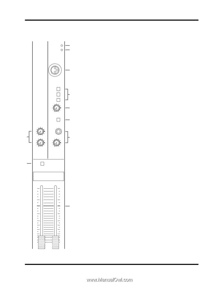
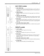
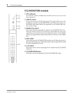
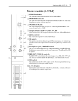
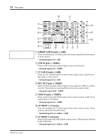
Master module (L-ST1-R) 9 Master module (L-ST1-R) POWER PHANTOM 1 POWER indicator 1 2 This indicator lights when the power switch is turned on. 2 PHANTOM indicator This indicator lights when the PHANTOM switch is turned on, indicating that phantom power is being supplied. TALKBACK IN 3 3 TALKBACK IN jack This is an unbalanced XLR type jack for connecting a talkback mic. The nominal input level is -50dB. GRP 1-4 AUX 1-4 ST 0 10 LEVEL TB 4 Assign switches (GRP 1-4, AUX 1-4, ST) 4 These switches select the output destination (mix bus) of the talkback mic. 5 LEVEL control This adjusts the signal level of the talkback mic. 5 6 TB switch This switch controls the talkback signal. When it is pressed, the talkback sig6 nal will be sent to the output destination selected by the assign switch located above. 7 Headphone jack / PHONES control 8 0 10 REC OUT 7 This is a 1/4" stereo phone jack for connecting a set of stereo headphones. Headphones connected here can be used to monitor PFL, AFL, and the 2TR 0 10 TAPE IN 0 10 PHONES IN signals. 8 REC OUT / TAPE IN controls 9 ON The REC OUT control adjusts the output signal level of the REC OUT jack. The TAPE IN control adjusts the input signal level of the TAPE IN jack. 9 ON switch This switch turns the ST1 OUT output on/off. When it is pressed in, the signal from the ST1 OUT jack will be output. 0 L-ST1-R faders 10 10 These faders control the level of the ST OUT output. A position at the zero (0) marking is the nominal output level. 5 5 0 0 0 5 5 10 10 15 15 20 20 25 25 30 30 40 40 ∞ ∞ L - ST 1 - R MX400 User's Guide
-
 1
1 -
2
-
3
-
4
-
5
-
6
-
7
-
 8
8 -
 9
9 -
 10
10 -
 11
11 -
 12
12 -
 13
13 -
 14
14 -
 15
15 -
 16
16 -
 17
17 -
 18
18 -
19
-
20
-
21
-
22
-
23
-
24
-
25
-
26
-
27
-
28
-
29
-
30
-
31
-
32
-
33
-
34
-
35
-
36
-
37
-
38
-
39
-
40
-
41
-
42
-
43
-
44
-
45
-
46
-
47
-
48
-
49
-
50
-
51
-
52
-
53
-
54
-
55
-
56
-
57
-
58
-
59
-
60
-
61
-
62
-
63
-
64
-
65
-
66
-
67
-
68
-
69
-
70
-
71
-
72
-
73
-
74
-
75
-
76
 |
 |