Yamaha RX 497 Owners Manual - Page 7
CONTROLS AND FUNCTIONS, Front panel - amplifier
 |
UPC - 027108923888
View all Yamaha RX 497 manuals
Add to My Manuals
Save this manual to your list of manuals |
Page 7 highlights
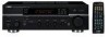
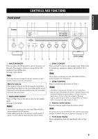
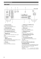
INTRODUCTION Front panel 1 2 CONTROLS AND FUNCTIONS CONTROLS AND FUNCTIONS 3 45 6 78 9 0 A B C D MASTER ON OFF MAIN ZONE ON/OFF INPUT ZONE 2 ON/OFF ZONE CONTROL FM/AM l TUNING/CH h XM/ANT EDIT MEMORY TUN MODE/DISP SEARCH MODE MAN'L/AUTO FM AUTO/MAN'L A/B/C/D/E 1 CATEGORY PHONES SPEAKERS A B 2 3 4 5 6 7 8 BASS 0 1 1 2 2 3 3 4 -5 4 5+ TREBLE 0 1 1 2 2 3 3 4 -5 4 5+ BALANCE 0 1 1 2 2 DISPLAY LOUDNESS FLAT 1 2 -30dB 10 3 3 3 9 4 L5 4 5R 4 8 5 7 6 PURE DIRECT MD/TAPE MONITOR VOLUME 16 20 12 26 8 40 4 60 ∞ -dB 2 0 E FG H I 1 MASTER ON/OFF Press inward to the ON position to turn on the power of this unit. Press again to release it outward to the OFF position to turn off this unit. See page 14 for details. Note Even when this unit is turned off, this unit consumes a small amount of power to preserve the memory. Memory back-up The memory back-up circuit prevents the stored data from being lost. However, the stored data will be lost if the power cord is disconnected from the AC wall outlet for more than one week. 2 MAIN ZONE ON/OFF Turns on Main Zone of this unit or sets it to the standby mode. See page 14 for details. Notes • This switch is operational only when MASTER ON/OFF is pressed inward to the ON position. • In the standby mode, this unit consumes a small amount of power to receive infrared signals from the remote control. (U.S.A. model) J K LM 3 ZONE 2 ON/OFF Turns on Zone 2 or set it to the standby mode. When Zone 2 is turned on, signals are output at the ZONE 2 OUT jacks. Note This switch is operational only when MASTER ON/OFF is pressed inward to the ON position. 4 ZONE CONTROL Press to control the input source of Zone 2. Notes • This button is operational only when Zone 2 is turned on. • When you press this button, the ZONE 2 indicator flashes in the front panel display for approximately 5 seconds. Select the input source of Zone 2 while the indicator is flashing. • You can select the preset station or channel when TUNER or XM is selected as the input source of Zone 2. 5 Remote control sensor Receives infrared signals from the remote control. Note Switch the remote control ID between ID1 and ID2 when using multiple YAMAHA receivers or amplifiers (see pages 35, 36). 6 Front panel display Shows information about the operational status of this unit. 3
-
 1
1 -
 2
2 -
 3
3 -
 4
4 -
 5
5 -
 6
6 -
 7
7 -
 8
8 -
 9
9 -
 10
10 -
 11
11 -
 12
12 -
13
-
14
-
15
-
16
-
17
-
18
-
19
-
20
-
21
-
22
-
23
-
24
-
25
-
26
-
27
-
28
-
29
-
30
-
31
-
32
-
33
-
34
-
35
-
36
-
37
-
38
-
39
-
40
-
41
-
42
-
43
-
44
-
45
-
46
-
47
-
48
-
49
-
50
-
51
-
52
-
53
 |
 |
