Yamaha RX-V1400 Owner's Manual - Page 25
Connecting the antennas, ohm/300-ohm antenna adapter, U.K. model only, FREQUENCY STEP switch
 |
View all Yamaha RX-V1400 manuals
Add to My Manuals
Save this manual to your list of manuals |
Page 25 highlights
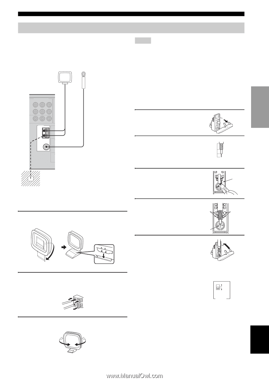
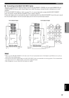
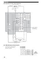
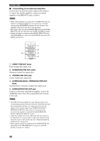
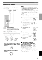
PREPARATION Connecting the antennas Both AM and FM indoor antennas are included with this unit. In general, these antennas should provide sufficient signal strength. Connect each antenna correctly to the designated terminals. AM loop antenna (included) Indoor FM antenna (included) COMPONENT VIDEO PR PB Y VD TV ONITOR OUT TUNER AM ANT GND MAIN FM ANT 75Ω UNBAL. SURRO SUB WOOFE Ground (GND terminal) For maximum safety and minimum interference, connect the antenna GND terminal to a good earth ground. A good earth ground is a metal stake driven into moist earth. ■ Connecting the AM loop antenna 1 Set up the AM loop antenna, then connect it to the terminals on this unit. CONNECTIONS Notes • The AM loop antenna should be placed away from this unit. • The AM loop antenna should always be connected, even if an outdoor AM antenna is connected to this unit. • A property installed outdoor antenna provides clearer reception than an indoor one. If you experience poor reception quality, an outdoor antenna may improve the quality. Consult the nearest authorized YAMAHA dealer or service center about outdoor antennas. ■ 75-ohm/300-ohm antenna adapter (U.K. model only) 1 Open the cover of the included 75-ohm/300-ohm antenna adapter. 2 Cut the external sleeve of the 75-ohm coaxial 11 (7/16) 8 (5/16) cable and prepare it for 6 (1/14) connection. Unit: mm (inch) 3 Cut the lead wire and remove it. Lead wire 4 Insert the cable wire into the slot, Clamp and clamp it with pliers. Insert the wire into slot. 5 Snap the cover into place. Clamp 2 Press and hold the tab to insert the AM loop antenna lead wires into the AM ANT and GND terminals. 3 Orient the AM loop antenna for the best reception. ■ FREQUENCY STEP switch (Asia and General models only) Because the interstation frequency spacing differs in different areas, set the FREQUENCY STEP switch (locating on the rear panel) according 100kHz/10kHz 50kHz/9kHz FM AM FREQUENCY STEP to the frequency spacing in your area. • North, Central and South America: 100 kHz/10 kHz • Other areas: 50 kHz/9 kHz Before setting this switch, disconnect this unit's AC power cord from the wall outlet. English 21
-
 1
1 -
2
-
3
-
4
-
5
-
6
-
7
-
8
-
9
-
10
-
11
-
12
-
13
-
14
-
15
-
16
-
17
-
18
-
19
-
 20
20 -
 21
21 -
 22
22 -
 23
23 -
 24
24 -
 25
25 -
 26
26 -
 27
27 -
 28
28 -
 29
29 -
 30
30 -
31
-
32
-
33
-
34
-
35
-
36
-
37
-
38
-
39
-
40
-
41
-
42
-
43
-
44
-
45
-
46
-
47
-
48
-
49
-
50
-
51
-
52
-
53
-
54
-
55
-
56
-
57
-
58
-
59
-
60
-
61
-
62
-
63
-
64
-
65
-
66
-
67
-
68
-
69
-
70
-
71
-
72
-
73
-
74
-
75
-
76
-
77
-
78
-
79
-
80
-
81
-
82
-
83
-
84
-
85
-
86
-
87
-
88
-
89
-
90
 |
 |