1996 Chevrolet Blazer Owner's Manual - Page 243
1996 Chevrolet Blazer Manual
Page 243 highlights
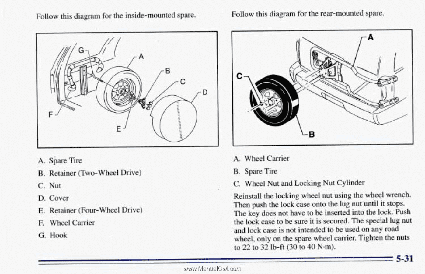
Follow this diagram for the inside-mounted spare. Follow this diagram for the rear-mounted spare. D A. Spare Tire A. Wheel Carrier B. C. D. E. Retainer (Two-Wheel Drive) Nut Cover Retainer (Four-wheel Drive) B. Spare Tire C. Wheel Nut and Locking Nut Cylinder Reinstall the locking wheel nut usingthe wheel wrench. Then push the lock case ontothe lug nut until it stops. The key does not have to be inserted into.the 1ock:Push the lock case to be sure it is secured. Thespecial lug nut and lock case is not intended to be used on any road wheel, only on the spare wheel carrier. Tighten the nuts to 22 to 32 lb-ft (30 to 40 N-m). E Wheel Carrier G . Hook 5-31
-
 1
1 -
2
-
3
-
4
-
5
-
6
-
7
-
8
-
9
-
10
-
11
-
12
-
13
-
14
-
15
-
16
-
17
-
18
-
19
-
20
-
21
-
22
-
23
-
24
-
25
-
26
-
27
-
28
-
29
-
30
-
31
-
32
-
33
-
34
-
35
-
36
-
37
-
38
-
39
-
40
-
41
-
42
-
43
-
44
-
45
-
46
-
47
-
48
-
49
-
50
-
51
-
52
-
53
-
54
-
55
-
56
-
57
-
58
-
59
-
60
-
61
-
62
-
63
-
64
-
65
-
66
-
67
-
68
-
69
-
70
-
71
-
72
-
73
-
74
-
75
-
76
-
77
-
78
-
79
-
80
-
81
-
82
-
83
-
84
-
85
-
86
-
87
-
88
-
89
-
90
-
91
-
92
-
93
-
94
-
95
-
96
-
97
-
98
-
99
-
100
-
101
-
102
-
103
-
104
-
105
-
106
-
107
-
108
-
109
-
110
-
111
-
112
-
113
-
114
-
115
-
116
-
117
-
118
-
119
-
120
-
121
-
122
-
123
-
124
-
125
-
126
-
127
-
128
-
129
-
130
-
131
-
132
-
133
-
134
-
135
-
136
-
137
-
138
-
139
-
140
-
141
-
142
-
143
-
144
-
145
-
146
-
147
-
148
-
149
-
150
-
151
-
152
-
153
-
154
-
155
-
156
-
157
-
158
-
159
-
160
-
161
-
162
-
163
-
164
-
165
-
166
-
167
-
168
-
169
-
170
-
171
-
172
-
173
-
174
-
175
-
176
-
177
-
178
-
179
-
180
-
181
-
182
-
183
-
184
-
185
-
186
-
187
-
188
-
189
-
190
-
191
-
192
-
193
-
194
-
195
-
196
-
197
-
198
-
199
-
200
-
201
-
202
-
203
-
204
-
205
-
206
-
207
-
208
-
209
-
210
-
211
-
212
-
213
-
214
-
215
-
216
-
217
-
218
-
219
-
220
-
221
-
222
-
223
-
224
-
225
-
226
-
227
-
228
-
229
-
230
-
231
-
232
-
233
-
234
-
235
-
236
-
237
-
 238
238 -
 239
239 -
 240
240 -
 241
241 -
 242
242 -
 243
243 -
 244
244 -
 245
245 -
 246
246 -
 247
247 -
 248
248 -
249
-
250
-
251
-
252
-
253
-
254
-
255
-
256
-
257
-
258
-
259
-
260
-
261
-
262
-
263
-
264
-
265
-
266
-
267
-
268
-
269
-
270
-
271
-
272
-
273
-
274
-
275
-
276
-
277
-
278
-
279
-
280
-
281
-
282
-
283
-
284
-
285
-
286
-
287
-
288
-
289
-
290
-
291
-
292
-
293
-
294
-
295
-
296
-
297
-
298
-
299
-
300
-
301
-
302
-
303
-
304
-
305
-
306
-
307
-
308
-
309
-
310
-
311
-
312
-
313
-
314
-
315
-
316
-
317
-
318
-
319
-
320
-
321
-
322
-
323
-
324
-
325
-
326
-
327
-
328
-
329
-
330
-
331
-
332
-
333
-
334
-
335
-
336
-
337
-
338
-
339
-
340
-
341
-
342
-
343
-
344
-
345
-
346
-
347
-
348
-
349
-
350
-
351
-
352
-
353
-
354
-
355
-
356
-
357
-
358
-
359
-
360
-
361
-
362
-
363
-
364
-
365
-
366
-
367
-
368
-
369
-
370
-
371
-
372
-
373
-
374
-
375
-
376
-
377
-
378
-
379
-
380
-
381
-
382
-
383
-
384
-
385
-
386
-
387
-
388
-
389
-
390
-
391
-
392
 |
 |
Follow this diagram
for
the
inside-mounted
spare.
D
A.
Spare Tire
B.
Retainer (Two-Wheel Drive)
C. Nut
D.
Cover
E.
Retainer
(Four-wheel
Drive)
E
Wheel Carrier
G.
Hook
Follow this diagram for the rear-mounted spare.
A.
Wheel Carrier
B.
Spare Tire
C. Wheel Nut and Locking Nut Cylinder
Reinstall the locking wheel
nut
using
the wheel wrench.
Then push the lock case
onto
the lug nut until it stops.
The key does not have to be inserted into.the 1ock:Push
the lock case
to
be sure it is secured.
The special lug nut
and lock case is not intended to
be used on
any
road
wheel, only
on the spare wheel
carrier. Tighten the nuts
to
22
to
32
lb-ft
(30
to
40
N-m).
5-31