Asus A7V8X-MX SE A7V8X-MX SE User's Manual - Page 13
ASUS A7V8X-MX SE motherboard user guide - memory
 |
View all Asus A7V8X-MX SE manuals
Add to My Manuals
Save this manual to your list of manuals |
Page 13 highlights
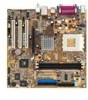
1 CPU socket. Socket 462 (Socket A) Zero Insertion Force (ZIF) socket for AMD Athlon XP™ up to 3200+ processors. 2 North bridge controller. The VIA KM400 North bridge controller chipset supports a 64-bit DDR memory controller and up to 2 GB of 333/266/200MHz DDR memory. It also incorporates the fast HyperTransport™ link to the CPU and supports AGP 8X technology. VIA KM400 also features the VIA UniChrome™ 2D/3D graphics core for efficient multimedia applications including DVD and video playback. 3 DDR DIMM sockets. The motherboard comes with two Double Data Rate Dual Inline Memory Module (DDR DIMM) sockets to support up to 2GB of system memory. This memory architecture allows data transfer rates of up to 2.7 GB/s with PC2700 DDR DIMMs. 4 ATX power connector. This connects the standard 20-pin plug from the power supply unit. The power supply unit must have at least 1A on the +5V standby lead (+5VSB). 5 DIP switches. This 5-pin Dual Inline Package (DIP) switches allows you to select the CPU frequency multiple. 6 Floppy disk drive connector. This connects the provided ribbon cable for the floppy disk drive. One side of the connector is slotted to prevent incorrect insertion of the floppy disk drive cable. 7 IDE connectors. These dual-channel bus master IDE connectors support up to four UltraATA133, PIO Modes 0 ~ 4 IDE devices. Both the primary (blue) and secondary (black) connectors are slotted to prevent incorrect insertion of the IDE ribbon cable. 8 AGP slot. The Accelerated Graphics Port (AGP) slot supports 1.5V and 0.8V AGP 8X/4X mode AGP cards for graphics and multimedia applications. 9 Flash EEPROM. This 2Mb Firmware Hub contains the programmable BIOS program. 10 Super I/O chipset. The Winbond 83697HF I/O controller offers support for a variety of I/O functions including two high-speed UART compatible serial ports and one parallel port with EPP and ECP capabilities. The Super I/O controller also supports a floppy disk drive, Game/MIDI port, PS/2 keyboard, and PS/2 mouse. 11 Onboard LED. This onboard LED lights up if there is a standby power on the motherboard. This LED acts as a reminder to turn off the system power before plugging or unplugging devices. ASUS A7V8X-MX SE motherboard user guide 1-5
-
 1
1 -
2
-
3
-
4
-
5
-
6
-
7
-
 8
8 -
 9
9 -
 10
10 -
 11
11 -
 12
12 -
 13
13 -
 14
14 -
 15
15 -
 16
16 -
 17
17 -
 18
18 -
19
-
20
-
21
-
22
-
23
-
24
-
25
-
26
-
27
-
28
-
29
-
30
-
31
-
32
-
33
-
34
-
35
-
36
-
37
-
38
-
39
-
40
-
41
-
42
-
43
-
44
-
45
-
46
-
47
-
48
-
49
-
50
-
51
-
52
-
53
-
54
-
55
-
56
-
57
-
58
-
59
-
60
-
61
-
62
-
63
-
64
 |
 |
