Asus P4PE-BP Motherboard DIY Troubleshooting Guide - Page 23
System memory - with dual cpu
 |
View all Asus P4PE-BP manuals
Add to My Manuals
Save this manual to your list of manuals |
Page 23 highlights
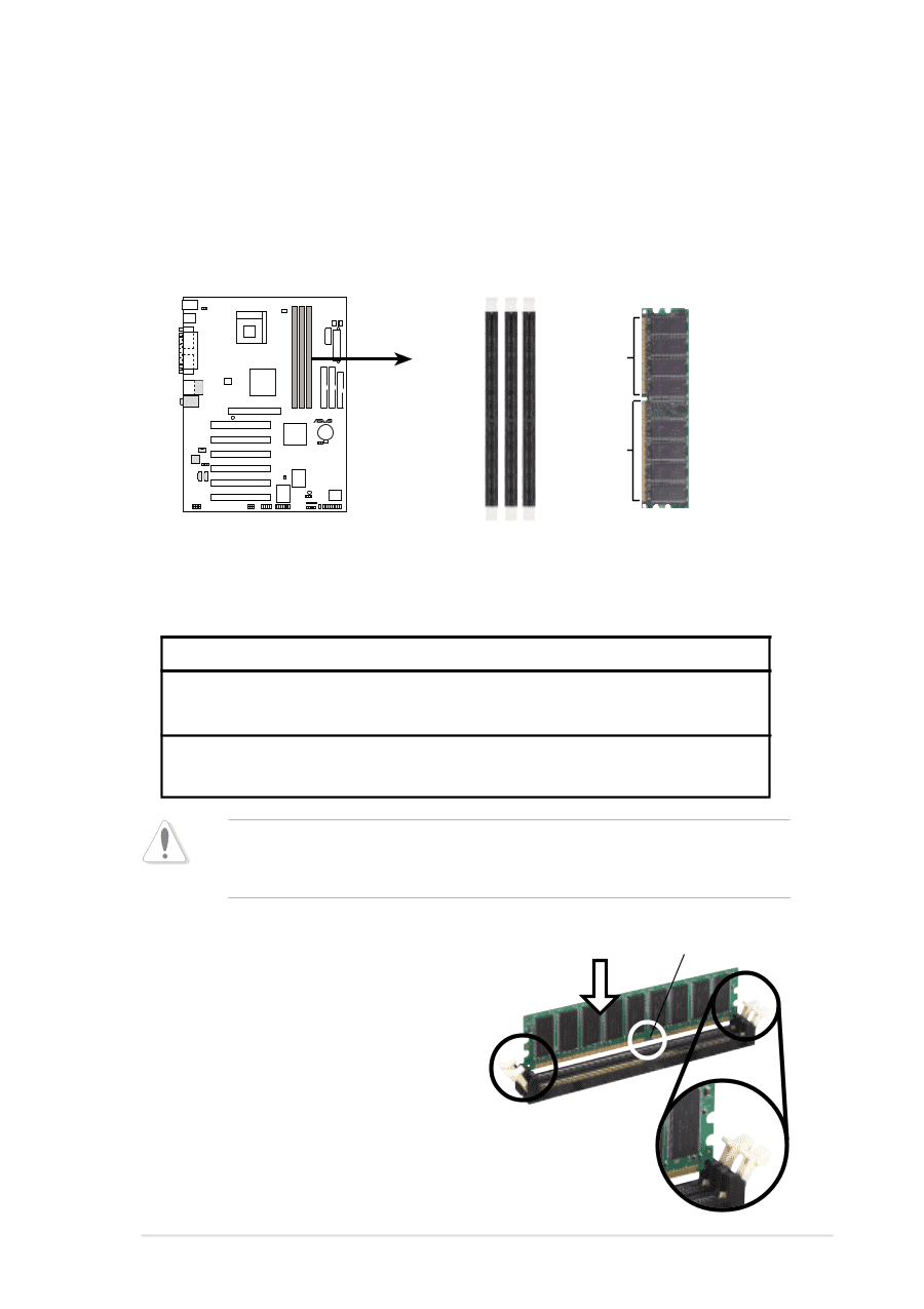
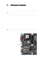
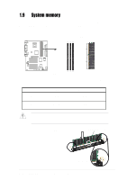
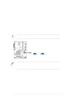
1.9 System memory The motherboard comes with three Double Data Rate (DDR) Dual Inline Memory Module (DIMM) sockets. These sockets support up to 2GB system memory using 184-pin unbuffered non-ECC PC2700/PC2100 (FSB533) or PC2100/PC1600 (FSB400) DDR DIMMs. The following figure illustrates the location of the DDR DIMM sockets. ® P4PE BP 80 Pins 104 Pins P4PE BP 184-Pin DDR DIMM Sockets This motherboard supports different memory frequencies depending on the CPU FSB (Front Side Bus) and the type of DDR DIMM. CPU FSB 533 MHz 400 MHz DDR DIMM Type PC2700 PC2100 PC2100 PC1600 Memory Frequency 333 MHz 266 MHz 266 MHz 200 MHz Make sure to unplug the power supply before adding or removing DIMMs or other system components. Failure to do so may cause severe damage to both the motherboard and the components. Follow these steps to install a DIMM. DDR DIMM notch 1. Unlock a DIMM socket by pressing the retaining clips outward. 2. Align a DIMM on the socket such that the notch on the DIMM matches the break on the socket. 3. Firmly insert the DIMM into the socket until the retaining clips snap back in place and the DIMM is properly seated. Unlocked Retaining Clip ASUS P4PE BP motherboard user guide 1-13
-
 1
1 -
2
-
3
-
4
-
5
-
6
-
7
-
8
-
9
-
10
-
11
-
12
-
13
-
14
-
15
-
16
-
17
-
 18
18 -
 19
19 -
 20
20 -
 21
21 -
 22
22 -
 23
23 -
 24
24 -
 25
25 -
 26
26 -
 27
27 -
 28
28 -
29
-
30
-
31
-
32
-
33
-
34
-
35
-
36
-
37
-
38
-
39
-
40
-
41
-
42
-
43
-
44
-
45
-
46
-
47
-
48
-
49
-
50
-
51
-
52
-
53
-
54
-
55
-
56
-
57
-
58
-
59
-
60
-
61
-
62
-
63
-
64
-
65
-
66
-
67
-
68
-
69
-
70
-
71
-
72
-
73
-
74
-
75
-
76
-
77
-
78
-
79
-
80
-
81
-
82
-
83
-
84
 |
 |