Asus PCH-DL User Manual - Page 22
Layout Contents - ram
 |
View all Asus PCH-DL manuals
Add to My Manuals
Save this manual to your list of manuals |
Page 22 highlights
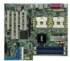
2.2.4 Layout Contents Sockets/Slots 1. CPU sockets 2. DDR DIMM sockets 3. PCI-X/PCI slots 4. AGP Pro slot Page 2-5 2-13 2-15 2-18 Jumpers 1. Keyboard power (3-pin KBPWR1) 2-19 2. CPU external frequency selection (3-pin J1) 2-19 3. IEEE 1394 setting (3-pin J3) 2-20 4. USB device wake-up (3-pin USBPW1, USBPW2) 2-20 5. RAID enable (3-pin J2) 2-21 6. Clear RTC RAM (3-pin CLRTC1) 2-21 Rear panel connectors 1. PS/2 mouse port 2-22 2. Parallel port 2-22 3. IEEE 1394 port 2-22 4. RJ-45 port 2-22 5. Line In port (light blue) 2-22 6. Line Out port (light green) 2-22 7. Microphone port (pink) 2-22 8. USB 2.0 ports 3 and 4 2-22 9. USB 2.0 ports 1 and 2 2-22 10. Serial ports 2-22 11. PS/2 keyboard port 2-22 Internal connectors 1. Floppy disk drive connector (34-1 pin FLOPPY1) 2-23 2. Serial ATA connectors (7-pin SATA1, SATA2) 2-23 3. IDE connectors (40-1 pin PRI_IDE[blue], SEC_IDE [black) 2-24 4. SMBus connector (6-1 pin SMB1) 2-24 5. RAID ATA/133/100/66/33 connector (40-1 pin PRI_RAID1) 2-25 6. Serial ATA RAID connectors (7-pin SATA_RAID1, SATA_RAID2) 2-26 7. SSI power connectors (24-pin, 8-pin) 2-27 8. Chassis intrusion connector (4-1 pin CHASSIS1) 2-28 9. IEEE 1394 connector (10-1 pin IEEE1394_1) 2-28 10. CPU, chassis, and system fan connectors (3-pin CHA_FAN1, CPU_FAN1/2, SYS_FAN1/2/3) 2-29 2-4 Chapter 2: Hardware information
-
 1
1 -
2
-
3
-
4
-
5
-
6
-
7
-
8
-
9
-
10
-
11
-
12
-
13
-
14
-
15
-
16
-
 17
17 -
 18
18 -
 19
19 -
 20
20 -
 21
21 -
 22
22 -
 23
23 -
 24
24 -
 25
25 -
 26
26 -
 27
27 -
28
-
29
-
30
-
31
-
32
-
33
-
34
-
35
-
36
-
37
-
38
-
39
-
40
-
41
-
42
-
43
-
44
-
45
-
46
-
47
-
48
-
49
-
50
-
51
-
52
-
53
-
54
-
55
-
56
-
57
-
58
-
59
-
60
-
61
-
62
-
63
-
64
-
65
-
66
-
67
-
68
-
69
-
70
-
71
-
72
-
73
-
74
-
75
-
76
-
77
-
78
-
79
-
80
-
81
-
82
-
83
-
84
-
85
-
86
-
87
-
88
-
89
-
90
-
91
-
92
-
93
-
94
-
95
-
96
-
97
-
98
-
99
-
100
 |
 |
