Asus TS100-E3 PI2 User Guide
Asus TS100-E3 PI2 Manual
 |
View all Asus TS100-E3 PI2 manuals
Add to My Manuals
Save this manual to your list of manuals |
Asus TS100-E3 PI2 manual content summary:
- Asus TS100-E3 PI2 | User Guide - Page 1
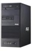
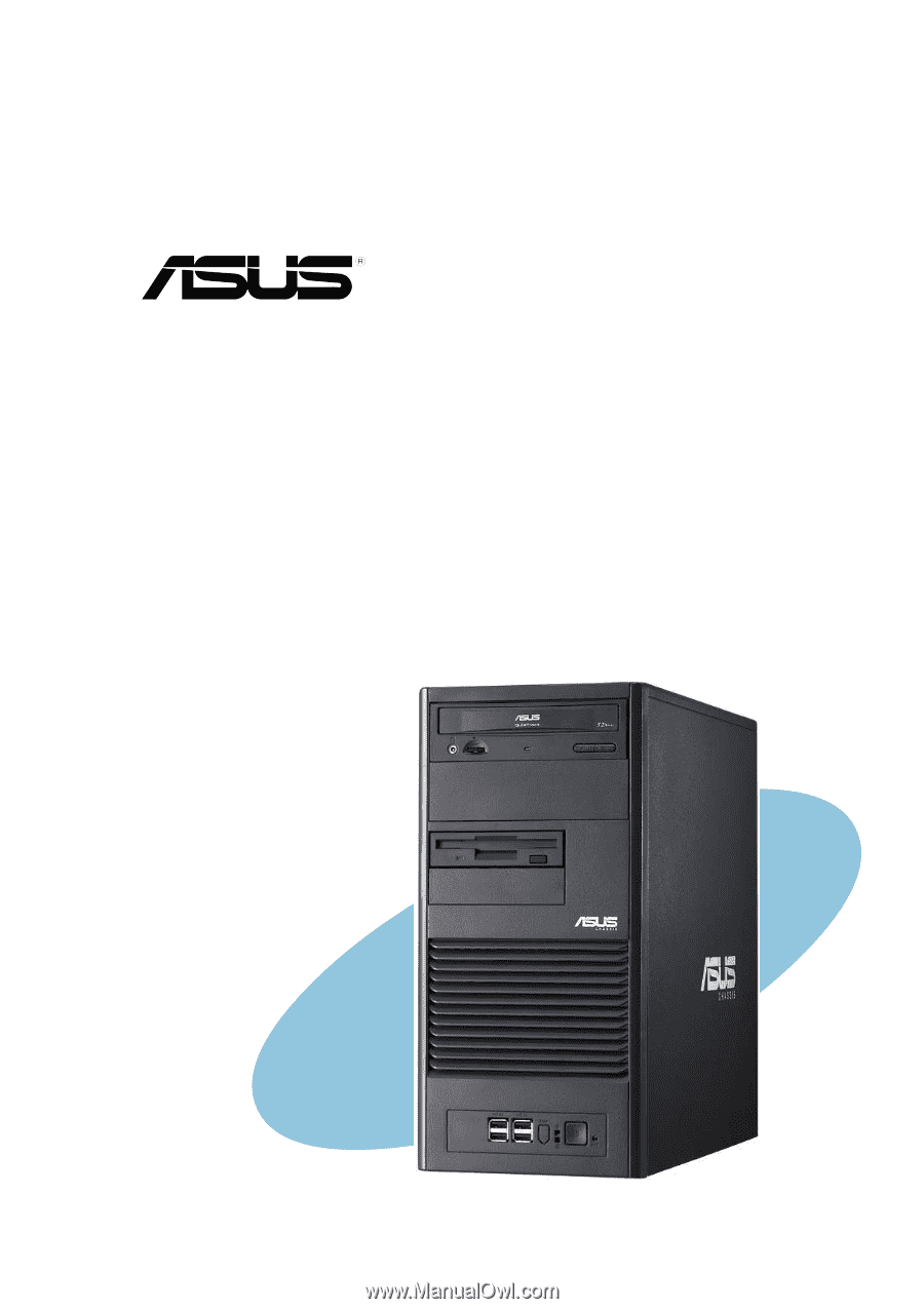
TS100-E3 Intel® Pentium® 4/Pentium® D LGA775 Pedestal Server 1066/800 MHz Front Side Bus - Asus TS100-E3 PI2 | User Guide - Page 2
, and should not be construed as a commitment by ASUS. ASUS assumes no responsibility or liability for any errors or inaccuracies that may appear in this manual, including the products and software described in it. Product warranty or service will not be extended if: (1) the product is repaired - Asus TS100-E3 PI2 | User Guide - Page 3
Contents Notices vii Safety information viii About this guide ix Chapter 1: Product introduction 1.1 System package contents 1-2 1.2 System specifications 1-3 1.3 Front panel features 1-5 1.4 Rear panel features 1-6 1.5 Internal features 1-7 1.6 LED information 1-8 Chapter 2: Hardware setup - Asus TS100-E3 PI2 | User Guide - Page 4
BIOS information 4.1 Managing and updating your BIOS 4-2 4.1.1 Creating a bootable floppy disk 4-2 4.1.2 AFUDOS utility 4-3 4.1.3 ASUS CrashFree BIOS 2 utility 4-5 4.1.4 ASUS Update utility 4-7 4.2 BIOS setup program 4-10 4.2.1 BIOS menu screen 4-11 4.2.2 Menu bar 4-11 4.2.3 Navigation keys - Asus TS100-E3 PI2 | User Guide - Page 5
Contents 4.3 Main menu 4-13 4.3.1 System Time 4-13 4.3.2 System Date 4-13 4.3.3 Legacy Diskette A 4-13 4.3.4 Primary/Secondary/Third IDE Master/Slave ......... 4-14 4.3.5 IDE Configuration 4-15 4.3.6 System Information 4-17 4.4 Advanced menu 4-18 4.4.1 USB Configuration 4-18 4.4.2 MPS - Asus TS100-E3 PI2 | User Guide - Page 6
2000/2003 Server 6-12 6.2.2 Red Hat® Enterprise ver. 3.0 6-13 6.3 Management applications and utilities installation 6-15 6.3.1 Running the support CD 6-15 6.3.2 Drivers menu 6-15 6.3.3 Management Software menu 6-16 6.3.4 Utilities menu 6-16 6.3.5 Contact information 6-16 Appendix: Reference - Asus TS100-E3 PI2 | User Guide - Page 7
. This equipment generates, uses and can radiate radio frequency energy and, if not installed and used in accordance with manufacturer's instructions, may cause harmful interference to radio communications. However, there is no guarantee that interference will not occur in a particular installation - Asus TS100-E3 PI2 | User Guide - Page 8
to fix it by yourself. Contact a qualified service technician or your dealer. Operation Safety • Any the server, carefully read all the manuals included with the server package. • Dispose of used batteries according to the manufacturer's instructions. CD-ROM Drive Safety Warning CLASS 1 LASER - Asus TS100-E3 PI2 | User Guide - Page 9
for system components. This chapter also describes the software applications that the barebone server supports. 7. Appendix: Reference information This section provides information about the power supply unit and a troubleshooting guide for solving common problems when using the barebone server. ix - Asus TS100-E3 PI2 | User Guide - Page 10
perform certain tasks properly, take note of the following symbols used throughout this manual. W A R N I N G : Information to prevent injury to components when trying to complete a task. I M P O R T A N T : Instructions that you MUST follow to complete a task. N O T E : Tips and information to - Asus TS100-E3 PI2 | User Guide - Page 11
Product introduction Chapter 1 This chapter describes the general features of the barebone server, including sections on the front panel and rear panel specifications. ASUS TS100-E3 1-1 - Asus TS100-E3 PI2 | User Guide - Page 12
cable • SATA signal cables • IDE cables System screws and cables System keys ( 2 pcs.) Bundled CDs • TS100-E3 support CD with ASWM* • Computer Associates® eTrust™ anti-virus CD Documentation • ASUS TS100-E3 user guide • ASUS ASWM 2.0 user guide Optional items • 52x IDE CD-ROM or 16X DVD-ROM drive - Asus TS100-E3 PI2 | User Guide - Page 13
1.2 System specifications The ASUS TS100-E3 is a barebone server system featuring the ASUS P5MT Series motherboard. The server supports an Intel® Pentium® 4/Pentium® D processor in the 775-land package, and includes the latest technologies through the chipsets embedded on the motherboard. Chassis - Asus TS100-E3 PI2 | User Guide - Page 14
supply 1 x Serial port 1 x Parallel port 1 x PS/2 keyboard port 1 x PS/2 mouse port 1 x LAN (RJ-45) ports 2 x USB 2.0 ports 1 x VGA port ASUS Server Web-based Management (ASWM) 2.0 Voltage, temperature, CPU and memory utilization, storage capacity, and fan speed monitoring Automatic Server Restart - Asus TS100-E3 PI2 | User Guide - Page 15
drive, and USB 2.0 ports are located on the front panel. For future installation of 5.25-inch devices, two drive bays are available. ASUS TS100-E3 D V D / CD - R O M d r i v e Empty 5.25-inch bay Floppy disk drive Empty 3.5-inch bay Power LED Power button Reset button HDD access LED USB 2.0 ports - Asus TS100-E3 PI2 | User Guide - Page 16
1.4 Rear panel features The rear panel includes a slot for the motherboard rear I/O ports, expansion slots, a chassis lock and intrusion switch, a vent for the system fan, and power supply module. Power connector PS/2 mouse port PS/2 keyboard port USB 2.0 ports Serial port Parallel port VGA port RJ - Asus TS100-E3 PI2 | User Guide - Page 17
motherboard, power supply, floppy disk, optical drive, and cables as shown. 1 2 3 5 6 7 8 4 1. Power supply module 2. Chassis fan 3. ASUS P5MT motherboard 4. Expansion card slots 5. Optical drive 6. 1 x 5.25-inch drive bay 7. Floppy drive 8. 2 x internal 3.5-inch drive bays ASUS TS100-E3 1-7 - Asus TS100-E3 PI2 | User Guide - Page 18
1.6 LED information The barebone system comes with five LED indicators. Refer to the following table for the LED status description. System and HDD LED Power LED (blue) Drive Status LED (green/red) LED System Power LED Icon Drive Status LED Display status ON Blinking Green Red Description - Asus TS100-E3 PI2 | User Guide - Page 19
Chapter 2 This chapter lists the hardware setup procedures that you have to perform when installing or removing system components. Hardware setup ASUS TS100-E3 2-1 - Asus TS100-E3 PI2 | User Guide - Page 20
2.1 Chassis cover The chassis features a "screwless design" that allows convenient assembly and disassembly. You can simply push or slide mechanical bolts and locks to remove the cover. 2.1.1 Removing the side cover 1. Remove the two screws that secure the cover to the chassis. 1 2. Slide the - Asus TS100-E3 PI2 | User Guide - Page 21
components to access the DIMM sockets and internal connectors. Refer to section "2.10 Removable components" for instructions. 2.1.2 Reinstalling the side cover To reinstall the side cover: 1. Match and insert the upper it snaps in place. 2 3. Re-screw to secure the side cover. 1 1 ASUS TS100-E3 2-3 - Asus TS100-E3 PI2 | User Guide - Page 22
P5MT-MX 2.2 Motherboard overview The barebone server comes with the P5MT-MX/C motherboard installed. The motherboard is secured to the chassis by eight (8) screws as indicated by the circles in the illustration below. Refer to "Chapter 4 Motherboard information" for detailed information on the - Asus TS100-E3 PI2 | User Guide - Page 23
of the socket box should face you. To prevent damage to the socket pins, do not remove the PnP cap unless you are installing a CPU. ASUS TS100-E3 2-5 - Asus TS100-E3 PI2 | User Guide - Page 24
3. Lift the load lever in the direction of the arrow to a 135º angle. 4. Lift the load plate with your thumb and forefinger to a 100º angle (A), then push the PnP cap from the load plate window to remove (B). B A Load plate 5. Position the CPU over the socket, making sure that the gold triangle - Asus TS100-E3 PI2 | User Guide - Page 25
retention tab. B The motherboard supports Intel® Pentium® 4 LGA775 processors with the Intel® Enhanced Memory 64 Technology (EM64T), Enhanced Intel SpeedStep® Technology (EIST), and Hyper-Threading Technology. Refer to the Appendix for more information on these CPU features. ASUS TS100-E3 2-7 - Asus TS100-E3 PI2 | User Guide - Page 26
2.3.2 Installing the CPU heatsink and airduct assembly The TS100-E3 comes with a proprietary CPU heatsink. You have to assemble the CPU heatsink before installing to the motherboard. To install the CPU heatsink and airduct assembly: 1. - Asus TS100-E3 PI2 | User Guide - Page 27
P5MT-MX/C CPU_FAN2 FANOUT7 FANPWR3 GND ® CPU_FAN1 FANOUT4 FANPWR2 GND P5MT-MX/C CPU Fan Connectors Do not forget to connect the CPU fan connector! Hardware monitoring errors may occur if you fail to plug the connector. ASUS TS100-E3 2-9 - Asus TS100-E3 PI2 | User Guide - Page 28
Double Data Rate II (DDR2) Dual Inline Memory Modules (DIMM) sockets to support 240-pin DDR modules. The figure illustrates the location of the DDR DIMM from the same vendor. Refer to the DDR2 Qualified Vendors List at the ASUS web site. • When installing one or two DIMMs, install the DIMM(s) - Asus TS100-E3 PI2 | User Guide - Page 29
: 1. Simultaneously press the retaining 2 clips outward to unlock the DIMM. Support the DIMM lightly with your fingers when pressing the retaining clips. The DIMM 1 might get damaged when it flips out with extra force. 1 DDR2 DIMM notch 2. Remove the DIMM from the socket. ASUS TS100-E3 2-11 - Asus TS100-E3 PI2 | User Guide - Page 30
Expansion slots In the future, you may need to install expansion cards. The following subsections describe the slots and the expansion cards that they support. Make sure to unplug the power cord before installing or removing expansion cards. Failure to do so may cause physical injury, and damage to - Asus TS100-E3 PI2 | User Guide - Page 31
PIRQE# REQ2# GNT2# PIRQD# PIRQB# When using PCI cards on shared slots, ensure that the drivers support "Shared IRQ" or that the cards do not need IRQ assignments. Otherwise, conflicts will arise between the two PCI groups, making the system unstableand the card inoperable. ASUS TS100-E3 2-13 - Asus TS100-E3 PI2 | User Guide - Page 32
to the limits of chipset, if users install a PCI Express X16 graphic card, the link speed will downgrade to x1. 2.5.5 PCI slots The PCI slots support cards such as a LAN card, SCSI card, USB card, and other cards that comply with PCI 2.3 specifications. The figure shows a LAN card installed on a 32 - Asus TS100-E3 PI2 | User Guide - Page 33
side rail. 2. Press each lock tab to release the front panel from the chassis. 3. Pull and swing the left edge of the front panel outward. ASUS TS100-E3 2-15 - Asus TS100-E3 PI2 | User Guide - Page 34
4. Unhook the hinge-like tabs from the holes on the right side of the front panel to completely detach the front panel assembly from the chassis. Do not use too much force when removing the front panel assembly. Hinge-like tab 2-16 Chapter 2: Hardware setup - Asus TS100-E3 PI2 | User Guide - Page 35
the left and fit the three hooked tabs to the left side of the chassis until the tabs snap back in place. 1 Hinge-like tab 1 1 2 ASUS TS100-E3 2-17 - Asus TS100-E3 PI2 | User Guide - Page 36
2.7 5.25-inch drives If you have powered up the system, make sure to unplug the AC power cable before installing or removing any system components. Failure to do so may cause damage to the motherboard and other system components! Two 5.25-inch drive bays are located on the upper front part of the - Asus TS100-E3 PI2 | User Guide - Page 37
back of the drive. 6. Connect a 4-pin plug from the power supply to the power connector on the back of the drive. IDE cable Power plug ASUS TS100-E3 2-19 - Asus TS100-E3 PI2 | User Guide - Page 38
hooked tabs on each side of the bay cover. 8. Reinstall the front panel assembly when done. Refer to section "2.5.2 Reinstalling the front panel assembly" for instructions. 2-20 Chapter 2: Hardware setup - Asus TS100-E3 PI2 | User Guide - Page 39
2.8 Hard disk drives 2.8.1 Removing a SATA HDD Follow the instructions in this section to remove a SATA hard disk drive (HDD). 1. First remove both side covers. 2. Then, unplug the SATA signal and power cables. 3. Unscrew the SATA HDD. 4. Remove the SATA HDD from the bay. ASUS TS100-E3 2-21 - Asus TS100-E3 PI2 | User Guide - Page 40
2.8.2 Installing a SATA HDD Follow the instructions in this section to install a SATA hard disk drive (HDD). 1. First remove both side covers. 2. Then, install the SATA HDD. 3. Secure the SATA HDD with screws. 4. Connect the SATA signal and power cables. 2-22 Chapter 2: Hardware setup - Asus TS100-E3 PI2 | User Guide - Page 41
the slot and its metal bracket to the slot opening on the chassis. 6. Press the card firmly until it is properly seated on the slot. ASUS TS100-E3 2-23 - Asus TS100-E3 PI2 | User Guide - Page 42
7. After installing the expansion card, put the metal bracket back. 8. Adjust the metal bracket to the locking pawl and screw it tightly. 2-24 Chapter 2: Hardware setup - Asus TS100-E3 PI2 | User Guide - Page 43
it. 4. Carefully remove the seated expansion card from the motherboard slot. 5. After removing the expansion card, re-screw the metal bracket to its original position. ASUS TS300-E3 2-25 - Asus TS100-E3 PI2 | User Guide - Page 44
2.10 Cable connections • The bundled system cables are pre-connected before shipped. You do not need to disconnect these cables unless you need to remove pre-installed components for additional device installation. • Refer to Chapter 4 for detailed information on the connectors. 2.10.1 Motherboard - Asus TS100-E3 PI2 | User Guide - Page 45
cable fon the REAR_FAN1 connector on the motherboard. 2. Locate the four screws that secure the fan to the chassis. 3. Remove the four screws while carefully supporting the chassis fan with your free hand to prevent it from falling off. Set the screws aside. 4. Carefully remove the chassis fan - Asus TS100-E3 PI2 | User Guide - Page 46
To reinstall the chassis fan: 1. Align the chassis fan holes to the screw holes on the chassis. 2. Drive in the four screws you removed earlier to secure the fan to the chassis. 3. Plug the chassis fan cable to the connector on the motherboard. 2-28 Chapter 2: Hardware setup - Asus TS100-E3 PI2 | User Guide - Page 47
can remove the floppy disk drive. Refer to section "2.5.1 Removing the front panel assembly" for instructions. To remove the floppy disk drive: 1. Disconnect the floppy disk cable and power cable from the secures the floppy disk. 3. Carefully pull out the drive from the chassis. ASUS TS300-E3 2-29 - Asus TS100-E3 PI2 | User Guide - Page 48
To install a floppy disk drive: 1. Position the floppy drive into the chassis until the drive fits the front edge of the bay. 2. Screw the floppy disk drive tightly. 3. Connect the drive signal cable and power cable. 2-30 Floppy drive power cable Floppy drive signal cable Red stripe to match Pin - Asus TS100-E3 PI2 | User Guide - Page 49
remove the front panel assembly before you can remove the front I/O board. Refer to section "2.5.1 Removing the front panel assembly" for instructions. To remove the front I/O board: 1. First, remove all the connected cables respectively. 2. Then, unscrew the front I/O board. 3. Last, remove the - Asus TS100-E3 PI2 | User Guide - Page 50
To install the front I/O board: 1. First, put the front I/O board into the chassis with caution. 2. Then, fasten the he front I/O board with screws. 3. Last, connect all the cables to the board respectively. 2-32 Chapter 2: Hardware setup - Asus TS100-E3 PI2 | User Guide - Page 51
connector) 3. 4-pin plug (optical drive) 4. 4-pinplug (floppy disk drive) Make sure to unplug A L L power cables from the system devices before removing the power supply unit. ASUS TS300-E3 2-33 - Asus TS100-E3 PI2 | User Guide - Page 52
To remove the power supply unit (PSU): 1. Remove the chassis cover. Refer to section "2.1.1 Removing the side cover." 2. Remove the front panel assembly. Refer to section "2.5.1 Removing the front panel assembly. 3. Lay the chassis on a flat, stable surface. 4. Disconnect all the power plug to the - Asus TS100-E3 PI2 | User Guide - Page 53
. 5. Secure the PSU to the chassis with the four screws you removed earlier. 6. Re-connect all the power plug to the connector inside the case. ASUS TS300-E3 2-35 - Asus TS100-E3 PI2 | User Guide - Page 54
2-36 Chapter 2: Hardware setup - Asus TS100-E3 PI2 | User Guide - Page 55
Chapter 3 This chapter gives information about the motherboard that comes with the server. This chapter includes the motherboard layout, jumper settings, and connector locations. Motherboard info ASUS TS100-E3 3-1 - Asus TS100-E3 PI2 | User Guide - Page 56
3.1 Motherboard layouts P5MT-MX/C model P5MT-MX/C DDR2 DIMM_A1 (64 bit,240-pin module) DDR2 DIMM_A2 (64 bit,240-pin module) DDR2 DIMM_B1 (64 bit,240-pin module) DDR2 DIMM_B2 (64 bit,240-pin module) PRI_IDE1 PS/2KBMS T: Mouse B: Keyboard KBPWR USB12 ATX12V1 USBPW12 COM1 24.5cm (9.6in) LGA775 - Asus TS100-E3 PI2 | User Guide - Page 57
sensor connector (2-pin TRPWR1) 12. System panel connector (20-pin PANEL1) Page 3-4 3-5 3-5 3-6 3-6 3-7 3-7 3-8 Page 3-10 3-10 3-11 3-12 3-12 3-13 3-13 3-14 3-14 3-15 3-15 3-16 ASUS TS100-E3 3-3 - Asus TS100-E3 PI2 | User Guide - Page 58
3.2 Jumpers The grayed out components in the illustrations may not be present in certain models. 1. Clear RTC RAM (CLRTC) This jumper allows you to clear the Real Time Clock (RTC) RAM in CMOS. You can clear the CMOS memory of date, time, and system setup parameters by erasing the CMOS RTC RAM data - Asus TS100-E3 PI2 | User Guide - Page 59
, the system would not power up. • If you are using Windows 2000, you need to install Service Pack 4 to wake up the system from S4 sleep mode. • The total current consumed must NOT exceed the power supply capability (+5VSB) whether under normal condition or in sleep mode. ASUS TS100-E3 3-5 - Asus TS100-E3 PI2 | User Guide - Page 60
4. Keyboard power (3-pin KBPWR1) This jumper allows you to enable or disable the keyboard wake-up feature. Set this jumper to pins 2-3 (+5VSB) to wake up the computer when you press a key on the keyboard (the default is the Space Bar). This feature requires an ATX power supply that can supply at - Asus TS100-E3 PI2 | User Guide - Page 61
caps to pins 2-3 for the Intel® Matrix Storage Manager. P5MT-MX/C ® RAID_SEL1 12 23 LSI RAID ROM INTEL RAID ROM (Default) P5MT-MX/C RAID_SEL1 Setting ASUS TS100-E3 3-7 - Asus TS100-E3 PI2 | User Guide - Page 62
8 . Force BIOS recovery setting (3-pin RECOVERY1) This jumper allows you to quickly update or recover the BIOS settings when it becomes corrupted. To update the BIOS: 1. Prepare a floppy disk that contains the latest BIOS for the motherboard (xxxx-xxx.ROM) and the AFUDOS.EXE utility. 2. Set the - Asus TS100-E3 PI2 | User Guide - Page 63
is for a PS/2 keyboard. Refer to the audio configuration table on the next page for the function of the audio ports in 2, 4, or 6-channel configuration. ASUS TS100-E3 3-9 - Asus TS100-E3 PI2 | User Guide - Page 64
3.3.2 Internal connectors 1 . Floppy disk drive connector (34-1 pin FLOPPY) This connector is for the provided floppy disk drive (FDD) signal cable. Insert one end of the cable to this connector, then connect the other end to the signal connector at the back of the floppy disk drive. Pin 5 on the - Asus TS100-E3 PI2 | User Guide - Page 65
LSI MegaRAID® utility embedded on the Intel® ICH7R Southbridge. (The server only support two HDD to using RAID 0, 1 configuration.) These connectors are set I Serial ATA • You must install Windows® 2000 Service Pack 4 or Windows® XP Service Pack 1 before using Serial ATA hard disk ASUS TS100-E3 3-11 - Asus TS100-E3 PI2 | User Guide - Page 66
this connector, then install the module to a slot opening at the back of the system chassis. This USB connector complies with USB 2.0 specification that supports up to 480 Mbps connection speed. P5MT-MX/C USB+5V USB_P7USB_P7+ GND NC GND USB_P2+ USB_P2USB+5V GND USB_P5+ USB_P5USB+5V ® USB34 P5MT - Asus TS100-E3 PI2 | User Guide - Page 67
caps only when you intend to use the chassis intrusion detection feature. P5MT-MX +5VSB_MB Chassis Signal GND CHASSIS1 (Default) P5MT-MX/C Chassis intrusion connector ASUS TS100-E3 3-13 - Asus TS100-E3 PI2 | User Guide - Page 68
8 . CPU, Chassis and power fan connectors (3-pin CPU_FAN1/2, REAR_FAN1/2, FRNT_FAN1/2) The fan connectors support cooling fans of 350 mA ~ 740 mA (8.88 W max.) or a total of 2.1 A ~ 4.44 A (53.28 W max.) at +12V. Connect the fan cables to the fan - Asus TS100-E3 PI2 | User Guide - Page 69
, connect the thermal sensor cable with a thermistor (of 1oK or at 25 oC, B=3435) to this connector. ® SYS-THEAMAL2 GND TRPWR1 P5MT-MX/C TRPWR Connector ASUS TS100-E3 3-15 - Asus TS100-E3 PI2 | User Guide - Page 70
12. System panel connector (20-pin PANEL1) This connector supports several chassis-mounted functions. • System power LED (Green 3-pin PLED) This 3-pin connector is for the system power LED. Connect the chassis power LED cable - Asus TS100-E3 PI2 | User Guide - Page 71
Chapter 4 This chapter tells how to change system settings through the BIOS Setup menus and describes the BIOS parameters. BIOS information ASUS TS100-E3 3-1 - Asus TS100-E3 PI2 | User Guide - Page 72
Updates the BIOS using a bootable floppy disk or the motherboard support CD when the BIOS file fails or gets corrupted.) 3. A S U S U original motherboard BIOS using the ASUS Update or AFUDOS utilities. the drive. b. At the DOS prompt, type format A:/S then press . Windows® XP environment - Asus TS100-E3 PI2 | User Guide - Page 73
afudos.exe) from the motherboard support CD to the bootable floppy ASUS V2.07(03.11.24BB)) Copyright (C) 2002 American Megatrends, Inc. All rights reserved. Reading flash ..... done Write to file...... ok A:\> The utility returns to the DOS prompt after copying the current BIOS file. ASUS TS100-E3 - Asus TS100-E3 PI2 | User Guide - Page 74
(www.asus.com) and download the latest BIOS file for the motherboard. Save the BIOS file to a bootable floppy disk. Write the BIOS filename on a piece of paper. You need to type the exact BIOS filename at the DOS prompt. 2. Copy the AFUDOS utility (afudos.exe) from the motherboard support CD to - Asus TS100-E3 PI2 | User Guide - Page 75
recovery... Checking for floppy... Floppy found! Reading file "P5MT-MX.ROM". Completed. Start flashing... DO NOT shut down or reset the system while updating the BIOS! Doing so will cause system boot failure! 4. Restart the system after the utility completes the updating process. ASUS TS100-E3 4-5 - Asus TS100-E3 PI2 | User Guide - Page 76
the support CD to the optical drive. 3. The utility displays the following message and automatically checks the floppy disk for the original or updated BIOS file. Bad this motherboard. Visit the ASUS website (www.asus.com) to download the latest BIOS file. 4-6 Chapter 4: Motherboard information - Asus TS100-E3 PI2 | User Guide - Page 77
from an updated BIOS file • Update the BIOS directly from the Internet • View the BIOS version information. This utility is available in the support CD that comes with the motherboard package. ASUS Update requires an Internet connection either through a network or an Internet Service Provider (ISP - Asus TS100-E3 PI2 | User Guide - Page 78
through the Internet To update the BIOS through the Internet: 1. Launch the ASUS Update utility from the Windows® desktop by clicking S t a r t > P r o g r a m s > A S U S > A S U S U p d a t e > A S U S U p d a t e. The ASUS Update main window appears. 2. Select Update BIOS from the 3. Select the - Asus TS100-E3 PI2 | User Guide - Page 79
A S U S U p d a t e. The ASUS Update main window appears. 2. Select Update BIOS from a file option from the drop-down menu, then click N e x t. 3. Locate the BIOS file from the O p e n window, then click S a v e. 4. Follow the screen instructions to complete the update process. ASUS TS100-E3 4-9 - Asus TS100-E3 PI2 | User Guide - Page 80
4.2 BIOS setup program This motherboard supports a programmable firmware chip that you can update using the provided exactly match what you see on your screen. • Visit the ASUS website (www.asus.com) to download the latest BIOS file for this motherboard. 4-10 Chapter 4: Motherboard information - Asus TS100-E3 PI2 | User Guide - Page 81
IDE Master Primary IDE Slave Third IDE Master Third IDE Slave Fourth IDE Master Fourth IDE Slave : [HDS722516VLSAB0] : [ASUS CD-S520/A4] : [Not Detected] : [Not Detected] : [Not Detected] : [Not Detected] System Information the navigation keys differ from one screen to another. ASUS TS100-E3 4-11 - Asus TS100-E3 PI2 | User Guide - Page 82
] [1.44M, 3.5 in] Primary IDE Master Primary IDE Slave Third IDE Master Third IDE Slave Fourth IDE Master Fourth IDE Slave : [HDS722516VLSAB0] : [ASUS CD-S520/A4] : [Not Detected] : [Not Detected] : [Not Detected] : [Not Detected] System Information Use [ENTER], [TAB], or [SHIFT-TAB] to select - Asus TS100-E3 PI2 | User Guide - Page 83
Fourth IDE Slave System Information [11:10:19] [Wed 11/02/2005] [1.44M, 3.5 in] : [HDS722516VLSAB0] : [ASUS CD-S520/A4] : [Not Detected] : [Not Detected] : [Not Detected] : [Not Detected] Use [ENTER]. 25 in.] [1.2M , 5.25 in.] [720K , 3.5 in.] [1.44M, 3.5 in.] [2.88M, 3.5 in.] ASUS TS100-E3 4-13 - Asus TS100-E3 PI2 | User Guide - Page 84
] [Auto] [CDROM] [ARMD] LBA/Large Mode [Auto] Enables or disables the LBA mode. Setting to [Auto] enables the LBA mode if the device supports this mode, and if the device was not previously formatted with LBA mode disabled. Configuration options: [Disabled] [Auto] 4-14 Chapter 4: BIOS setup - Asus TS100-E3 PI2 | User Guide - Page 85
UTILITY IDE Configuration Configure SATA As [Standard IDE] Onboard IDE Operate Mode [Enhanced Mode] Enhanced Mode Support On [S-ATA] IDE Detect Time Out (Sec) [35] When in AHCI/RAID mode SATA to [RAID] or [AHCI]. Configuration options: [Standard IDE] [AHCI] [RAID] ASUS TS100-E3 4-15 - Asus TS100-E3 PI2 | User Guide - Page 86
MS-DOS. Configuration options: [Disabled] [Compatible Mode] [Enhanced Mode] Enhanced Mode Support On [S-ATA Mode] The default of this item is [S-ATA]. This mode [P-ATA] are special options for advanced users. If compatible problems emerge, please restore the mode to the default. Configuration - Asus TS100-E3 PI2 | User Guide - Page 87
, Inc. AMI BIOS Displays the auto-detected BIOS information. Processor Displays the auto-detected CPU specification. System Memory Displays the auto-detected total system memory. ASUS TS100-E3 4-17 - Asus TS100-E3 PI2 | User Guide - Page 88
BIOS SETUP UTILITY USB Configuration MPS Configuration Remote Access Configuration CPU Configuration Chipset Onboard Devices Configuration PCI/PnP Configure the USB support. Select Screen Select Item +- Change Option F1 General Help F10 Save and Exit ESC Exit v02.58 (C)Copyright 1985-2004 - Asus TS100-E3 PI2 | User Guide - Page 89
USB Ports] [4 USB Ports] [6 USB Ports] [8 USB Ports] Legacy USB Support [Auto] Allows you to enable or disable support for legacy USB devices. Setting to [Auto] allows the system to detect the you to select the multi-processor system version. Configuration options: [1.1] [1.4] ASUS TS100-E3 4-19 - Asus TS100-E3 PI2 | User Guide - Page 90
] Terminal Type [ANSI] Allows you to set up the terminal type. Configuration options: [ANSI] [VT100] [VT-UTF8] VT-UTF8 Combo Key Support [Disabled] Allows you to enable or disable VT-UTF8 Combo Key Support under ANSI or VT-100. Configuration options: [Disabled] [Enabled] 4-20 Chapter 4: BIOS setup - Asus TS100-E3 PI2 | User Guide - Page 91
Thermal Control [Auto] When this item is set to [Auto], BIOS automatically checks the CPU capability to enable TM or TM2 support. In TM mode, the CPU has lower power consumption. In TM2 mode, the CPU core ratio and VID is reduced. Configuration options: [Auto] [Disabled] ASUS TS100-E3 4-21 - Asus TS100-E3 PI2 | User Guide - Page 92
you to enable or disable the Hyper-Threading Technology of CPU. Configuration options: [Disabled] [Enabled] When an Intel Pentium4 processor which supports Hyper-Threading Technology is installed, this functioin will then work. Intel(R) Speedstep Technology [Automatic] Allows you to set up enchanced - Asus TS100-E3 PI2 | User Guide - Page 93
are set according to the DRAM SPD (Serial Presence Detect). When disabled, you can manually set the DRAM timing parameters through the DRAM sub-items. The following sub-items appear when options: [TC1]~[TC7] PEG Force x1 [Disabled] Configuration options: [Disabled] [Enabled] ASUS TS100-E3 4-23 - Asus TS100-E3 PI2 | User Guide - Page 94
Memory Remap Feature [Disabled] Allows you to remap the overlap PCI memory over the total physical memory. Configuration options: [Disabled] [Enabled] 4.4.6 Onboard Devices Configuration Advanced BIOS SETUP UTILITY Configure Win627EHF Super IO Chipset Serial Port1 Address Serial Port2 Address - Asus TS100-E3 PI2 | User Guide - Page 95
IRQ is free for use of PCI/PnP devices. When set to [Reserved], the IRQ is reserved for legacy devices. Configuration options: [PCI Device] [Reserved] ASUS TS100-E3 4-25 - Asus TS100-E3 PI2 | User Guide - Page 96
Advanced Power Management (APM) features. Select an item then press to display the configuration options. Main Advanced Power ACPI APIC Support APM Configuration Hardware Monitor BIOS SETUP UTILITY Boot Exit [Enabled] Include ACPI APIC table pointer to RSDT pointer list. Select Screen - Asus TS100-E3 PI2 | User Guide - Page 97
Card or Modem Riser Card. This feature requires an ATX power supply that provides at least 1A on the +5VSB lead. Configuration options: [Disabled] [Enabled] ASUS TS100-E3 4-27 - Asus TS100-E3 PI2 | User Guide - Page 98
4.5.3 Hardware Monitor Hardware Monitor Power BIOS SETUP UTILITY CPU1 Temperature MB Temperature CPU Fan1 Speed CPU Fan2 Speed Front Fan1 Speed Front Fan2 Speed Rear Fan1 Speed Rear Fan2 Speed [34ºC/93ºF] [28ºC/82ºF] [4530RPM] [N/A] [N/A] [N/A] [N/A] [N/A] Smart Fan Control CPU Target - Asus TS100-E3 PI2 | User Guide - Page 99
Voltage, 3.3V Voltage, 5V Voltage, 5VSB Voltage, VBAT Voltage, 12V Voltage The onboard hardware monitor automatically detects the voltage outputs through the onboard voltage regulators. ASUS TS100-E3 4-29 - Asus TS100-E3 PI2 | User Guide - Page 100
Priority 1st Boot Device 2nd Boot Device 3rd Boot Device BIOS SETUP UTILITY Boot [1st FLOPPY DRIVE] [HDD:3M-HDS722516VL] [CD-ROM:PS-ASUS CD-S] Specifies the boot sequence from the available devices. A device enclosed in parenthesis has been disabled in the corresponding menu. Select Screen Select - Asus TS100-E3 PI2 | User Guide - Page 101
Support [Auto] Allows you to enable or disable support for PS/2 mouse. Configuration options: [Disabled] [Enabled] [Auto] Wait for 'F1' If Error [Enabled] When set to Enabled, the system waits for the F1 key to be pressed when error occurs. Configuration options: [Enabled] [Disabled] ASUS TS100-E3 - Asus TS100-E3 PI2 | User Guide - Page 102
Hit 'DEL' Message Display [Enabled] When set to Enabled, the system displays the message "Press DEL to run Setup" during POST. Configuration options: [Enabled] [Disabled] Interrupt 19 Capture [Enabled] When set to [Enabled], this function allows the option ROMs to trap Interrupt 19. Configuration - Asus TS100-E3 PI2 | User Guide - Page 103
, you can clear it by erasing the CMOS Real Time Clock (RTC) RAM. See section "3.2 Jumpers" for information on how to erase the RTC RAM. ASUS TS100-E3 4-33 - Asus TS100-E3 PI2 | User Guide - Page 104
After a supervisor password is set, the other items appear to allow you to change other security settings. BIOS SETUP UTILITY Boot Security Settings Supervisor Password : Installed User Password : Not Installed Change Supervisor Password User Access Level Change User Password Clear User - Asus TS100-E3 PI2 | User Guide - Page 105
> to save your changes and exit Setup. If you wish to cancel the command, select [Cancel] then press to return to the Exit menu. ASUS TS100-E3 4-35 - Asus TS100-E3 PI2 | User Guide - Page 106
Exit & Discard Changes Select this option then press to exit the Setup utility without saving your changes. When a confirmation window appears, select [OK] then press to discard your changes and exit Setup. If you wish to cancel the command, select [Cancel] then press to - Asus TS100-E3 PI2 | User Guide - Page 107
RAID Configuration Chapter 5 This chapter provides information on how toconfigure your hard disk drives as RAID sets. ASUS TS100-E3 3-1 - Asus TS100-E3 PI2 | User Guide - Page 108
benefits. If you want to boot the system from a hard disk drive included in a created RAID set, copy first the RAID driver from the support CD to a floppy disk before you install an operating system to the selected hard disk drive. Refer to Chapter 6 for details. 5-2 Chapter 5: RAID configuration - Asus TS100-E3 PI2 | User Guide - Page 109
SATA hard disks into the drive bays following the instructions in the system user guide. 2. Connect a SATA signal cable to the signal d S A T A R A I D S e t u p U t i l i t y if you installed SATA hard disk drives on the SATA connectors supported by the Intel® ICH7R Southbridge. ASUS TS100-E3 5-3 - Asus TS100-E3 PI2 | User Guide - Page 110
Embedded SATA RAID Setup Utility allows you to create RAID 0 and RAID 1 set(s) from SATA hard disk drives connected to the SATA connectors supported by the motherboard ICH7R Southbridge chip. To enter the LSI Logic Embedded SATA RAID Setup Utility: 1. Turn on the system after installing all the - Asus TS100-E3 PI2 | User Guide - Page 111
1 only). In N e w C o n f i g u r a t i o n, you manually set the logical drive parameters and assign the set size and stripe size (RAID 1 only). Using Easy Configuration o n f i g u r e, then press . 2. Use the arrow keys to select Easy Configuration, then press . ASUS TS100-E3 5-5 - Asus TS100-E3 PI2 | User Guide - Page 112
3. The ARRAY SELECTION MENU displays the available drives connected to the SATA ports. Select the drives you want to include in the RAID set, then press . When selected, the drive indicator changes from R E A D Y to ONLIN A[X]-[Y], where X is the array number, and Y is the drive number. - Asus TS100-E3 PI2 | User Guide - Page 113
5. Press , select the configurable array, then press . The logical drive information appears including a Logical Drive menu that allows you to change the logical drive parameters. ASUS TS100-E3 5-7 - Asus TS100-E3 PI2 | User Guide - Page 114
6. Select R A I D from the L o g i c a l D r i v e menu, then press . 7. Select the RAID level from the menu, then press . You need at least two identical hard disk drives when creating a RAID 1 set. 8. When creating a RAID 1 set, select S t r i p e S i z e from the L o g i c a l D r - Asus TS100-E3 PI2 | User Guide - Page 115
>. 12. Follow steps 5 to 10 to configure additional logical drives. 13. When prompted, save the configuration, then press to return to the Management Menu. ASUS TS100-E3 5-9 - Asus TS100-E3 PI2 | User Guide - Page 116
Using a New Configuration Use New Configuration to clear the existed RAID setup. If you don't want to clear the existed setup, use View/Add Configuration option to view or add a new RAId setup. Follow the steps below and set up a RAID with Easy Configuration. 1. From the Management Menu, highlight C - Asus TS100-E3 PI2 | User Guide - Page 117
A[X]-[Y], where X is the array number, and Y is the drive number. The information of the selected hard disk drive displays at the bottom of the screen. ASUS TS100-E3 5-11 - Asus TS100-E3 PI2 | User Guide - Page 118
4. Select all the drives required for the RAID set, then press . The configurable array appears on screen. 5. Press , select the configurable array, then press . The logical drive information appears including a Logical Drive menu that allows you to change the logical drive - Asus TS100-E3 PI2 | User Guide - Page 119
press . 8. Key-in the desired logical drive size, then press . 9. Follow steps 8 to 13 of the C r e a t i n g a R A I D s e t : U s i n g E a s y C o n f i g u r a t i o n section to add the new RAID configuration. ASUS TS100-E3 5-13 - Asus TS100-E3 PI2 | User Guide - Page 120
5.2.3 Initializing the logical drives After creating the RAID set(s), you must initialize the logical drives. You may initialize the logical drives of a RAID set(s) using the I n i t i a l i z e or O b j e c t s command on the Management Menu. Using the Initialize command To initialize the logical - Asus TS100-E3 PI2 | User Guide - Page 121
the drive without confirmation. Initializing a logical drive(s) erases all data on the drive. 4. A progress bar appears on screen. If desired, press to abort initialization. ASUS TS100-E3 5-15 - Asus TS100-E3 PI2 | User Guide - Page 122
5. When initialization is completed, press . Using the Objects command To initialize the logical drives using the O b j e c t s command: 1. From the Management Menu, highlight O b j e c t s, then press . 5-16 Chapter 5: RAID configuration - Asus TS100-E3 PI2 | User Guide - Page 123
2. Select Logical Drive from the O b j e c t s sub-menu, then press . 3. Select the logical drive to initialize from the L o g i c a l D r i v e s sub-menu, then press . 4. Select Initialize from the pop-up menu, then press to start initialization. ASUS TS100-E3 5-17 - Asus TS100-E3 PI2 | User Guide - Page 124
5. When prompted, press the to select Y e s from the I n i t i a l i z e ? dialog box, then press . You may also press to initialize the drive without confirmation. 6. A progress bar appears on screen. If desired, press to abort initialization. 7. When initialization is - Asus TS100-E3 PI2 | User Guide - Page 125
5.2.4 Rebuilding failed drives You can manually rebuild failed hard disk drives using the R e b u i l d command in the I V E S S E L E C T I O N M E N U displays the available drives connected to the SATA ports. Select the drive you want to rebuild, then press . ASUS TS100-E3 5-19 - Asus TS100-E3 PI2 | User Guide - Page 126
3. After selecting the drive to rebuild, press . The indicator for the selected drive now shows R B L D. 4. When prompted, press to to rebuild the drive. 5. When rebuild is complete, press any key to continue. 5-20 Chapter 5: RAID configuration - Asus TS100-E3 PI2 | User Guide - Page 127
(s) and prompts you to select the logical drive to check. Use the arrow keys to select the logical drive from the L o g i c a l D r i v e selection, then press . ASUS TS100-E3 5-21 - Asus TS100-E3 PI2 | User Guide - Page 128
3. When prompted, press the to select Y e s from the C o n s i s t e n c y C h e c k dialog box, then press . You may also press to check the drive consistency. A progress bar appears on screen. 4. While checking the disk consistency, press to display the following - Asus TS100-E3 PI2 | User Guide - Page 129
from the pop-up menu, then press . 4. When prompted, press to to check the drive. 5. When checking is complete, press any key to continue. ASUS TS100-E3 5-23 - Asus TS100-E3 PI2 | User Guide - Page 130
5.2.6 Deleting a RAID configuration To delete a RAID configuration: 1. From the Management Menu, select Configure > Clear Configuration, then press . 2. When prompted, press the to select Y e s from the C l e a r C o n f i g u r a t i o n ? dialog box, then press . The - Asus TS100-E3 PI2 | User Guide - Page 131
> to select the bootable logical drive from the list, then press . 3. The logical drive is selected as boot drive. Press any key to continue. ASUS TS100-E3 5-25 - Asus TS100-E3 PI2 | User Guide - Page 132
You may also create a RAID set(s) in Windows® operating environment using the Global Array Manager (GAM) application. The GAM application is available from the motherboard support CD. Refer to the GAM user guide in the motherboard support CD for details. 5-26 Chapter 5: RAID configuration - Asus TS100-E3 PI2 | User Guide - Page 133
Driver installation Chapter 6 This chapter provides information on RAID configurations, RAID driver installation, and LAN driver installation for this motherboard. ASUS TS100-E3 3-1 - Asus TS100-E3 PI2 | User Guide - Page 134
boot priority to boot from the support CD. Save your changes, then TS100-E3/P12 FRu 6. Place a blank, high-density floppy disk to the floppy disk drive, then select the type of RAID driver disk you want to create by typing the number before the option 7. Press . 8. Follow screen instructions - Asus TS100-E3 PI2 | User Guide - Page 135
s® 2 0 0 0 / 2 0 0 3 S e t u p starts. 2. Press when the message "P r e s s F 6 i f y o u n e e d t o i n s t a l l a t h i r d p a r t y S C S I o r R A I D d r i v e r . . ." appears at the bottom of the screen. 3. When prompted, press to specify an additional device. ASUS TS100-E3 6-3 - Asus TS100-E3 PI2 | User Guide - Page 136
the RAID controller drivers from the RAID driver disk. When prompted, press to continue installation. 7. Setup then proceeds with the OS installation. Follow screen instructions to continue. 6-4 Chapter 6: Driver installation - Asus TS100-E3 PI2 | User Guide - Page 137
e a r c h f o r a s u i t a b l e d r i v e r f o r m y d e v i c e ( r e c o m m e n d e d ), then click N e x t. 10. The wizard searches the RAID controller drivers. When found, click N e x t to install the drivers. 11. Click F i n i s h after the driver installation is done. ASUS TS100-E3 6-5 - Asus TS100-E3 PI2 | User Guide - Page 138
To verify the RAID controller driver installation: 1. Right-click the M y C o m p u t e r icon on the Windows® desktop , then select P r o p e r t i e s from the menu. 2. Click the H a r d w a r e tab, then click the D e v i c e M a n a g e r button. 3. Click the "+" sign before the item S C S I a n - Asus TS100-E3 PI2 | User Guide - Page 139
Red Hat® Enterprise ver. 3.0 To install the Intel® ICH7R LSI Logic Embedded SATA RAID controller driver when installing Red Hat® Enterprise ver. 3.0 OS: 1. Boot the system from the Red Hat® Installation CD. 2. At the boot:, type linux dd , then press . ASUS TS100-E3 6-7 - Asus TS100-E3 PI2 | User Guide - Page 140
3. Select Y e s using the key when asked if you have the driver disk. Press 4. Select f d 0 using the key when asked to select the driver disk source. Press to move the cursor to O K, then press . 6-8 Chapter 6: Driver installation - Asus TS100-E3 PI2 | User Guide - Page 141
for the RAID controller are installed to the system. 6. When asked if you will load additional RAID controller drivers, select N o, then press . 7. Follow screen instructions to continue the OS installation. ASUS TS100-E3 6-9 - Asus TS100-E3 PI2 | User Guide - Page 142
RAID controller driver when installing SuSE Linux OS: 1. Boot the system from the SuSE Installation CD. 2. Select Installation from the B o o t O p t i o n s menu, then press . 3. A message instructs you to prepare the RAID driver disk. Press . 6-10 Chapter 6: Driver installation - Asus TS100-E3 PI2 | User Guide - Page 143
4. When prompted, insert the RAID driver disk to the floppy disk drive, then press . 5. When prompted, select the floppy disk drive (fd0) as the driver update medium, select OK, then press . The drivers for the RAID controller are installed to the system. ASUS TS100-E3 6-11 - Asus TS100-E3 PI2 | User Guide - Page 144
driver installation This section provides instructions on how to install l to close this window. • If A u t o r u n is NOT enabled in your computer, browse the contents of the support CD to locate the file ASSETUP.EXE from the BIN folder. Double-click the A S S E T U P . E X E to run the CD. 3. - Asus TS100-E3 PI2 | User Guide - Page 145
when the InstallShield Wizard window appears. Follow screen instructions to continue installation. 6.2.2 Red Hat® Enterprise ver. 3.0 Follow these instructions when installing the Broadcom® Gigabit LAN controller base distributions that has an older version of the driver. ASUS TS100-E3 6-13 - Asus TS100-E3 PI2 | User Guide - Page 146
Install first the K e r n e l D e v e l o p m e n t tools before building the driver from the TAR file. To build the driver from the TAR file: 1. Create a directory and extract the TAR files: tar xvzf bcm5700-.tar.gz 2. Build the driver bcm5700.o as a loadable module for the running kernel - Asus TS100-E3 PI2 | User Guide - Page 147
the system detects installed devices. Install the necessary drivers to activate the devices. The screen display and driver options vary under different operating system versions. ASUS TS100-E3 6-15 - Asus TS100-E3 PI2 | User Guide - Page 148
menu The U t i l i t i e s menu displays the software applications and utilities that the motherboard supports. Click on an item to install. 6.3.5 Contact information Click the C o n t a c t tab to display the ASUS contact information. You can also find this information on the inside front cover of - Asus TS100-E3 PI2 | User Guide - Page 149
Reference information Appendix This section provides information about the power supply unit and a troubleshooting guide for solving common problems when using the barebone server. ASUS TS100-E3 3-1 - Asus TS100-E3 PI2 | User Guide - Page 150
A.1 350 W single power supply A.1.1 General description The 350 W SSI-type single power supply with universal AC input includes PFC and ATX-compliant output cables and connectors. The power supply has 9 plugs. Take note of the devices to which you should connect the plugs. 24P P 2 P 3 P 4 P 5 P 7 - Asus TS100-E3 PI2 | User Guide - Page 151
A.1.2 Specifications Input Characteristics Input Voltage Range Normal Range Auto Range Input Frequency Range 110 to 127 V ~ 10 A 200 to 240 V ~ 5 A 50 Hz to 60 Hz DC Output characteristics Output Voltage +3.33V +5V +12V -12V -5V +5VSB Max (A) 24 24 43 0.5 0.5 2.0 ASUS TS100-E3 A-3 - Asus TS100-E3 PI2 | User Guide - Page 152
or the components. These problems only requires simple troubleshooting actions that you can perform by yourself. Problem Action T h e po Check the memory modules and make sure you installed the DIMMs the system supports. Make sure that the DIMMs are properly installed on the sockets. Check the
-
 1
1 -
 2
2 -
 3
3 -
 4
4 -
 5
5 -
 6
6 -
 7
7 -
8
-
9
-
10
-
11
-
12
-
13
-
14
-
15
-
16
-
17
-
18
-
19
-
20
-
21
-
22
-
23
-
24
-
25
-
26
-
27
-
28
-
29
-
30
-
31
-
32
-
33
-
34
-
35
-
36
-
37
-
38
-
39
-
40
-
41
-
42
-
43
-
44
-
45
-
46
-
47
-
48
-
49
-
50
-
51
-
52
-
53
-
54
-
55
-
56
-
57
-
58
-
59
-
60
-
61
-
62
-
63
-
64
-
65
-
66
-
67
-
68
-
69
-
70
-
71
-
72
-
73
-
74
-
75
-
76
-
77
-
78
-
79
-
80
-
81
-
82
-
83
-
84
-
85
-
86
-
87
-
88
-
89
-
90
-
91
-
92
-
93
-
94
-
95
-
96
-
97
-
98
-
99
-
100
-
101
-
102
-
103
-
104
-
105
-
106
-
107
-
108
-
109
-
110
-
111
-
112
-
113
-
114
-
115
-
116
-
117
-
118
-
119
-
120
-
121
-
122
-
123
-
124
-
125
-
126
-
127
-
128
-
129
-
130
-
131
-
132
-
133
-
134
-
135
-
136
-
137
-
138
-
139
-
140
-
141
-
142
-
143
-
144
-
145
-
146
-
147
-
148
-
149
-
150
-
151
-
152
 |
 |
Intel
Intel
Intel
Intel
Intel
®
Pentium
Pentium
Pentium
Pentium
Pentium
®
4/Pentium
4/Pentium
4/Pentium
4/Pentium
4/Pentium
®
D LGA775
D LGA775
D LGA775
D LGA775
D LGA775
Pedestal
Pedestal
Pedestal
Pedestal
Pedestal Server
Server
Server
Server
Server
1066/800 MHz Front Side Bus
TS100-E3