Behringer X32-TP User Manual - Page 39
X32 Main Display, 7.1 Overview, Overview
 |
View all Behringer X32-TP manuals
Add to My Manuals
Save this manual to your list of manuals |
Page 39 highlights
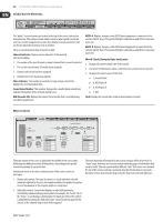
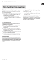
39 X32 DIGITAL MIXER Preliminary User Manual 7. X32 Main Display 7.1 Overview 7.1.1 Display and Navigation Controls The controls in this section are used in conjunction with the color screen, in order to navigate and control the graphical elements it contains. By including dedicated rotary controllers that correspond to adjacent controls on the screen, as well as including cursor buttons, the user can quickly navigate and control all of the color screen's elements. Color Screen: This color screen contains various displays that give visual feedback for the operation of the console, and also allow the user to make various adjustments not provided for by the dedicated hardware controls. Rotary Encoders: These six rotary encoders are used to adjust various color screen elements located directly above them. Each of the six rotary encoders can be pushed inward to activate a button press function. This function is useful when controlling color screen elements that have a dual "on/off" type state that is best controlled by a button, as opposed to a variable state that is best adjusted by a rotary control. Screen selection buttons: These 8 illuminated buttons allow the user to immediately navigate to any of 8 master screens that address different sections of the console. The 8 sections that can be navigated to with these buttons are: 1. Home 2. Meters 3. Routing 4. Setup 5. Library 6. Effects 7. Mute Group 8. Utility Page Select Buttons: These two buttons allow for left-right navigation among the different "pages" contained within a screen set. A graphical tab display shows which page you are currently on. Layer Up/Down Buttons: On some screens, there are more parameters present than can be adjusted by the 6 encoders underneath. In these cases, use the layer up/down buttons to navigate through any additional layers contained on the screen page. L/R Meter: This dual 24-segment meter displays the audio signal level output from the main bus of the console. M/C SOLO Meter: This dual 24-segment meter displays the audio signal level output from the mono bus of the console. When one or more channels are currently soloed, the meter switches to displaying the level of the currently soloed signal(s). 7.1.2 Console Screens The color screen of the X32 offers a wealth of visual feedback and hands on control for the console. Whereas the dedicated top panel controls offer immediate hands-on adjustments for the most important operations of a channel, the color screens offer similarly immediate visual feedback for a selected channel, as well as more global areas of the console. The screens are divided into three main areas: 1. Global Screen Elements 2. Main Display 3. Rotary Encoder Elements
-
 1
1 -
2
-
3
-
4
-
5
-
6
-
7
-
8
-
9
-
10
-
11
-
12
-
13
-
14
-
15
-
16
-
17
-
18
-
19
-
20
-
21
-
22
-
23
-
24
-
25
-
26
-
27
-
28
-
29
-
30
-
31
-
32
-
33
-
 34
34 -
 35
35 -
 36
36 -
 37
37 -
 38
38 -
 39
39 -
 40
40 -
 41
41 -
 42
42 -
 43
43 -
 44
44 -
45
-
46
-
47
-
48
-
49
-
50
-
51
-
52
-
53
-
54
-
55
-
56
-
57
-
58
-
59
-
60
-
61
-
62
-
63
-
64
-
65
-
66
-
67
-
68
-
69
-
70
 |
 |
