Behringer X32-TP User Manual - Page 41
Navigation Methods, Dedicated Screens, Rotary Encoder Elements, For example
 |
View all Behringer X32-TP manuals
Add to My Manuals
Save this manual to your list of manuals |
Page 41 highlights
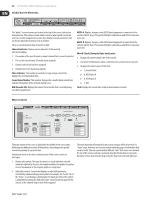
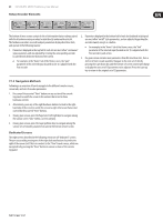
41 X32 DIGITAL MIXER Preliminary User Manual Rotary Encoder Elements: Gain +0.00 dB Link Lo Cut 20 Hz Lo Cut Source Input Select Delay 0.3 ms Delay Ins Pos PRE Insert Insert InsF Connect The bottom of most screens contain 6 slots of information that are always paired with the 6 hardware rotary encoders located directly underneath each slot. The hardware encoders are used to adjust parameters displayed in these slots, and operate in the following manner: 1. Parameters displayed in the top half of each slot are most often "continuous" type parameters, and are adjusted by rotating the corresponding encoder located directly below the bottom of the screen. • For example, in the "home" tab of the Home screen, the "gain" parameter of the selected input (located in slot 1) is adjusted with the first encoder. 2. Parameters displayed in the bottom half of each slot (outlined in dark grey) are most often "on/off" style parameters, and are adjusted by pushing the encoder inward, using it as a button. • For example, in the "home" tab of the Home screen, the "link" parameter of the selected input (located in slot 1) is adjusted with the first encoder's push action. 3. If a given screen contains more parameters than fits into the 6 slots, then a 2nd set of slots is made available. Navigate to the next set of slots by pressing the Layer down key, and the bottom-of-screen content will change to display the next set of 12 parameters to be adjusted. Press the Layer up key to return to the original set of 12 parameters. 7.1.3 Navigation Methods Following is an overview of how to navigate to the different console screens, screen tabs, and sets of encoder parameters. 1. Press any of the assorted "View" buttons on any section of the console top panel to switch the screen to the content that is tied to those hardware controls. 2. Alternatively, press any of the eight hardware buttons located to the righthand side of the screen to switch the screen to eight other areas that are not covered by the assorted "View" buttons. 3. On any given screen, press the Page Select left/right keys to navigate among the various screen "tabs" within a screen category. 4. On any given screen, press the Layer up/down keys to navigate among the various sets of encoder parameters located at the bottom of each screen. Dedicated Screens The eight screens described in the following section are all "dedicated" screens. They are accessed by pressing one of the eight dedicated buttons located to the right of the screen itself. This is in contrast to the "View" based screens, which are navigated to by pressing the "View" button in various sections of the console top panel.
-
 1
1 -
2
-
3
-
4
-
5
-
6
-
7
-
8
-
9
-
10
-
11
-
12
-
13
-
14
-
15
-
16
-
17
-
18
-
19
-
20
-
21
-
22
-
23
-
24
-
25
-
26
-
27
-
28
-
29
-
30
-
31
-
32
-
33
-
34
-
35
-
 36
36 -
 37
37 -
 38
38 -
 39
39 -
 40
40 -
 41
41 -
 42
42 -
 43
43 -
 44
44 -
 45
45 -
 46
46 -
47
-
48
-
49
-
50
-
51
-
52
-
53
-
54
-
55
-
56
-
57
-
58
-
59
-
60
-
61
-
62
-
63
-
64
-
65
-
66
-
67
-
68
-
69
-
70
 |
 |
