Behringer X32-TP User Manual - Page 7
Soundcard, Main Display Area, Monitoring and Talkback, Group/Bus Channel Banks
 |
View all Behringer X32-TP manuals
Add to My Manuals
Save this manual to your list of manuals |
Page 7 highlights
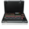
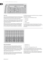
7 X32 DIGITAL MIXER Preliminary User Manual On each fader strip you will find a motorized 100 mm level fader, Mute and Solo buttons, a Gate indicator, an input level meter, Compressor indicator, and the channel select button. Each of the 16 input channels has an individual (and customizable) color LCD screen that can display a channel number, nickname, and even a graphical channel icon. In the event that a channel's input source has been changed to an input signal that differs from the default setup, the LCD display will also indicate the name of the actual input source. Ch01 Aux5 PC Soundcard Example: Channel 01 has the nickname Soundcard and is fed from Aux input 5. Ch01 FatSnare 01 OpeningScene 02: next home con g 0:00 gate - 0:00 dyn A: S16 B: - eq 15:33 A: 48K C: XUF : 15 sends main Main Display Area The main color display presents information about various sections of the console. It can be switched to different screens using the console's View buttons, as well as any of the 8 buttons on the right side of the display. The top section of the main display permanently covers useful status information. The top left corner shows the selected channel number, its nickname and the selected icon. The next block shows the current scene number and name in amber, as well as the next upcoming scene. The center section displays the playback file name along with elapsed and remaining time and a recorder status icon. The next block to the right has 4 segments to show the status of AES50 ports A and B, the Card slot and the audio clock synchronization source and sample rate (top right). Small green square indicators show proper connectivity. The right most block shows the console time that can be set under Setup/Config. When working with any given screen, press the Page keys located on the display bezel to switch to different screen pages. Editing parameters or settings on each of the screens is done using the 6 associated push-encoders along the bottom edge of the display. • Whenever there is a continuous control or list entry, you can turn the corresponding knob for editing, which is indicated by various circular icons • When there is a switch or toggle function on one of these knobs, you will see a broad rectangular button along the lower edge of the field. Pressing the encoder changes the on/off state of the corresponding function. When the rectangular button in the display is dark grey, the corresponding function is off/inactive; when it is amber, the function is on/active Monitoring and Talkback There are two separate Level controls in this section, one for the headphone outputs located on either side of the console, and a second one for the monitor outputs located on the rear panel. Press the section's View button to edit various monitoring preferences, such as the input source for the phones bus and the monitor outputs. This section also contains independent Talkback buttons (A and B). Press the View button to edit the Talkback preferences for the Talkback A path and Talkback B path separately. This screen also contains settings for the optional goose-neck lamp and the console's internal test-tone generator. Group/Bus Channel Banks VIEW This section of the console offers eight channel strips, divided into the -6 following layers: • Eight DCA (digitally controlled amplifier) groups • Mix Bus masters 1-8 • Mix Bus masters 9-16 • Matrix Outputs 1-6, and the main center bus VIEW This section also contains a main LR output fader, which is independent and always available no matter which channel bank or layer is active. When using the DCA Groups layer, the DCA Groups can be soloed and muted, but they cannot be selected. To edit the DCA group names, icons and colors, navigate to the Setup/DCA Groups page on the main display. When using any of the output bus layers, note that the bottom LEDs on the meters in this section illuminate when the respective bus is fed from pre-fader sources of the selected channel.
-
 1
1 -
 2
2 -
 3
3 -
 4
4 -
 5
5 -
 6
6 -
 7
7 -
 8
8 -
 9
9 -
 10
10 -
 11
11 -
 12
12 -
13
-
14
-
15
-
16
-
17
-
18
-
19
-
20
-
21
-
22
-
23
-
24
-
25
-
26
-
27
-
28
-
29
-
30
-
31
-
32
-
33
-
34
-
35
-
36
-
37
-
38
-
39
-
40
-
41
-
42
-
43
-
44
-
45
-
46
-
47
-
48
-
49
-
50
-
51
-
52
-
53
-
54
-
55
-
56
-
57
-
58
-
59
-
60
-
61
-
62
-
63
-
64
-
65
-
66
-
67
-
68
-
69
-
70
 |
 |
