Biostar M7VIP M7VIP user's manual
Biostar M7VIP Manual
 |
View all Biostar M7VIP manuals
Add to My Manuals
Save this manual to your list of manuals |
Biostar M7VIP manual content summary:
- Biostar M7VIP | M7VIP user's manual - Page 1
M7VIP FCC Statement and Copyright This energy and, if not installed and used in accordance with the instructions, may cause harmful interference to radio communications. There is no guarantee found in this user's manual. All the brand and product names are trademarks of their respective companies. i - Biostar M7VIP | M7VIP user's manual - Page 2
Jumpers, Headers, Connectors & Slots 9 ESPAÑOL 15 Características del M7VIP 15 Contenido del Paquete 16 Disposición del M7VIP (Para Versión 1.0 17 Disposición del M7VIP (Para Versiones 1.1 en adelante 18 Instalación de la CPU...19 Módulos DDR DIMM: DIMM1-2-3 20 Puentes, Cabezales, Conectores - Biostar M7VIP | M7VIP user's manual - Page 3
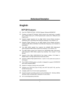
DDeessccrriippttiioonn English M7VIP Features ! Use VIA VT8367 (KT333) / VT8235 Chipset, Winbond W83697HF. ! Contains on board I/O facilities, which include two serial ports, a parallel port, a PS/2 mouse port, a PS/2 keyboard port, audio ports, USB ports and a game port. ! Supports Single Socket - Biostar M7VIP | M7VIP user's manual - Page 4
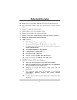
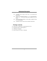
Audio out for 6 channels Audio. ! Support front audio pin head functions. ! Support wake up from USB keyboard/ mouse. ! Support 3 ports firewire 1394 function (Optional). ! Support with PCI specification v2.2. # Integrated 400 Mbit 3-Port PHY. # Supports provisions of IEEE 1394-1995 Standard. - Biostar M7VIP | M7VIP user's manual - Page 5
with the latest PCI IDE, ATA 7 and enhanced IDE specifications. # Supports ATA proprosal PIO Mode 0, 1, 2, 3, 4, Ultra DMA Mode 0, contents ! HDD Cable X 1, FDD Cable X 1, Fully Setup Driver CD X 1 ! Flash Memory Writer for BIOS update X 1 ! USB Cable X 2 (Optional) ! Rear I/O Panel for ATX Case - Biostar M7VIP | M7VIP user's manual - Page 6
MMootthheerrbbooaarrdd DDeessccrriippttiioonn Layout of M7VIP (For Version 1.0) 11 JKBV1 JUSBV1 CPU Socket A DIMM1 DIMM2 DIMM3 1 JATXPWR1 1 VT8367 (KT333) MIC-IN LINE-IN SP-OUT GAME Port JGAME1 1 CMI9739 Winbond I/O JAUDIO1 1 BIOS AGP SLOT PCI1 PCI SLOT J D I M M VOLT 1 8 2 7 1 IDE1 - Biostar M7VIP | M7VIP user's manual - Page 7
MMootthheerrbbooaarrdd DDeessccrriippttiioonn Layout of M7VIP (For Version 1.1 and above) 11 JKBV1 JUSBV1 CPU Socket A DIMM1 DIMM2 DIMM3 1 JATXPWR1 1 VT8367 (KT333) MIC-IN LINE-IN SP-OUT GAME Port JGAME1 1 CMI9739 Winbond I/O JAUDIO1 1 BIOS AGP SLOT PCI1 PCI SLOT JD I MMVO LT 1 8 2 7 1 - Biostar M7VIP | M7VIP user's manual - Page 8
Pin A in the socket and lock for the white dot or cut edge in the CPU. Match Pin A with the white dot/cut edge then insert the CPU. 3. Press the lever down. Then Put the fan on the CPU and buckle it and put the fan's power port into the JCFAN1, then to - Biostar M7VIP | M7VIP user's manual - Page 9
. If not, change the CPU fan, and then restart the system. DDR DIMM Modules: DIMM1-2-3 DRAM Access Time: 2.5V Unbuffered/ Registered DDR 1600/ 2100/ 2700 Type required. DRAM Type: 64MB/ 128MB/ 256MB/ 512MB/ 1GB DIMM Module (184 pin) DIMM Socket Location DDR Module Total Memory Size (MB) DIMM - Biostar M7VIP | M7VIP user's manual - Page 10
can only fit into the slot in one direction. 2. Push the tabs out. Insert the DIMM memory modules into the socket at a 90-degree angle, then push down vertically so that it will fit into the place. 3. The Mounting Holes and plastic - Biostar M7VIP | M7VIP user's manual - Page 11
card interface, which supports audio, and modem only. Peripheral Component Interconnect Slots: PCI1-5 This motherboard is equipped with 5 Port Slot: AGP1 Your monitor will attach directly to that video card. This motherboard supports video cards for PCI slots, but it is also equipped with an - Biostar M7VIP | M7VIP user's manual - Page 12
additional IDE devices. However, it can only support master mode IDE HDD. Power Connectors: JATXPWR1 (ATXJMAaTJiAnXTPPoXWwPeRWr C1Ron1n.) (ATX Power Conn.) Wake On LAN Header: JWOL1 Ground 5V_SB Wake up 1 WOL1 Front USB Header: JUSB1/ JUSB2/ JUSB3 Pin1,2 ==> +5V 2 Pin3,4 ==> Data(-) 1 Pin5 - Biostar M7VIP | M7VIP user's manual - Page 13
MMootthheerrbbooaarrdd DDeessccrriippttiioonn 5V/ 5VSB Selection for USB: JUSBV1/2/3 1 JUSBV1/2/3 Pin 1-2 on ==> 5V Pin 2-3 on ==> 5V_SB 5V/ 5VSB Selection for KB: JKBV1 1 Pin 1-2 on ==> 5V JKBV1 Pin 2-3 on ==> 5V_SB Front 1394 Header: J1394A1/ - Biostar M7VIP | M7VIP user's manual - Page 14
MMootthheerrbbooaarrdd DDeessccrriippttiioonn CPU Frequency Selection: JCLK1 4 6 Pin 1-2, 5-6 ==> 100 Mhz Pin 2-3, 5-6 ==> 133 Mhz 13 (default) JCLK1 Pin 2-3, 4-5 ==> 166Mhz (For Version 1.1 and above) 1 Pin 1-2 ==> 100 Mhz JCLK1 Pin 2-3 ==> 133 Mhz ( - Biostar M7VIP | M7VIP user's manual - Page 15
(-) SPK RST IR HLED SPK ==> Speaker Conn. HLED ==> Hard Driver LED RST ==> Reset Button IR ==> Infrared Conn. SLP ==> Sleep Button ON/ OFF ==> Power-on Button Audio Subsystem: JAUDIO1/ JCDIN1 1 JAUDIO1 2 (Front Audio Header) 1 JCDIN1 (CD-ROM Audio-In Header) 2 1 JAUDIO1 Pin1 - Biostar M7VIP | M7VIP user's manual - Page 16
are available for front panel audio connectors. 9 10 Clear CMOS Jumper: JCMOS1 1 Pin 1-2 on ==> Normal Operation (default) JCMOS1 Pin 2-3 on ==> Clear CMOS Data Back Panel Connectors JKBMS1 PS/2 Mouse JUSB1 JPRNT1 Parallel JGAME1 Game Port PS/2 Keyboard USB COM1 JCOM1 COM2 JCOM2 - Biostar M7VIP | M7VIP user's manual - Page 17
del M7VIP ! Usa Chipsets VIA VT8367 (KT333)/ VT8235 y Winbond W83697HF. ! Contiene facilidades I/O integrados en la placa madre en el que incluye dos puertos en serie, un puerto paralelo, un puerto para el ratón PS/2, un puerto para teclado PS/2, puertos de audio, puertos USB y puerto de juego - Biostar M7VIP | M7VIP user's manual - Page 18
ATA y Raid (Opcional). ! Soporta función over speed/ voltage (Opcional). Contenido del Paquete ! Cable HDD X 1, Cable FDD X 1, Configuración completa del Driver CD X 1 ! Flash Memory Writer para actualización del BIOS X 1 ! Cable USB X 2 (Opcional) ! Panel trasero I/O para caja ATX X 1 (Opcional) 16 - Biostar M7VIP | M7VIP user's manual - Page 19
Disposición del M7VIP (Para Versión 1.0) 11 JKBV1 JUSBV1 CPU Socket A DIMM1 DIMM2 DIMM3 Entrada Entrada Salida del del MIC de Linea Altavoz Puerto de Juego 1 JATXPWR1 1 VT8367 (KT333) JGAME1 1 Ranura AGP PCI1 Ranura PCI J D I M M VOLT 1 8 2 7 1 IDE1 IDE2 FDD1 CMI9739 BIOS Ranura PCI - Biostar M7VIP | M7VIP user's manual - Page 20
del M7VIP (Para Versiones 1.1 en adelante) 11 JKBV1 JUSBV1 CPU Socket A DIMM1 DIMM2 DIMM3 Entrada Entrada Salida del del MIC de Linea Altavoz Puerto de Juego 1 J AT X P W R 1 1 VT8367 (KT333) JGAME1 1 Ranura AGP PCI1 Ranura PCI J D IM M V O LT 1 8 2 7 1 IDE1 IDE2 FDD1 C MI 97 39 BIOS - Biostar M7VIP | M7VIP user's manual - Page 21
y busque el punto blanco o corte el borde en la CPU. Empareje el contacto A con el punto blanco/ corte del borde, luego inserte la CPU. 3. Presione la palanca para abajo. Ponga el ventilador en la CPU y abróchelo. Luego ponga el puerto de corriente del ventilador en el JCFAN1. Y ya habrá completado - Biostar M7VIP | M7VIP user's manual - Page 22
. Si esta situación ocurre, por favor asegúrese que el ventilador de la CPU esté funcionando correctamente. Si no, cambie el ventilador de la CPU y vuelva a iniciar el sistema. Módulos DDR DIMM: DIMM1-2-3 DRAM Tiempo de Acceso: 2.5V Unbuffered/ Registered DDR 1600/ 2100/ 2700 Tipo requerido. DRAM - Biostar M7VIP | M7VIP user's manual - Page 23
Cómo instalar un Módulo DIMM 1. El zócalo DIMM tiene una lengüeta plástica de seguridad y el módulo de memoria DIMM tiene una muesca asimétrica, así el módulo de memoria DIMM puede caber solamente en la ranura de una sóla dirección. 2. Tire la lengüeta hacia afuera. Inserte los módulos - Biostar M7VIP | M7VIP user's manual - Page 24
ía del AGP para el mejoramiento de la eficiencia y funcionamiento del video, especialmente con gráficos 3D. Conector Serial ATA: (JSATA1/ JSATA2) (Opcional) Ésta placa madre contiene un PCI junto a un controlador SATA con 2 canales de interface SATA, que satisface el spec de SATA 1.0 y también puede - Biostar M7VIP | M7VIP user's manual - Page 25
puede usar las características del IDE para configurar la configuración de un disk array y para soportar dispositivos adicionales del IDE. Sin Conector de Corriente: JATXPWR1 JATXPWR1 (Conector de Corriente ATX) Cabezal Wake On LAN: JWOL1 Tierra 5V_SB Wake up 1 WOL1 Cabezal Frontal USB: JUSB1 - Biostar M7VIP | M7VIP user's manual - Page 26
,4 ==> Dato(-) Contacto5,6 ==> Dato(+) JUSB1/2 Contacto7,8 ==> Tierra Contacto9 ==> KEY (Para Version 1.0) Contacto10 ==> NA 5V/ 5VSB Selección para USB: JUSBV1/2/3 1 Contacto 1-2 on ==> 5V JUSBV1/2/3 Contacto 2-3 on ==> 5V_SB 5V/ 5VSB Selección para KB: JKBV1 1 Contacto 1-2 on ==> 5V - Biostar M7VIP | M7VIP user's manual - Page 27
MMootthheerrbbooaarrdd DDeessccrriippttiioonn Selección de la Frecuencia del CPU: JCLK1 4 6 1 3 JCLK1 Contacto 1-2, 5-6 ==> 100 Mhz Contacto 2-3, 5-6 ==> 133 Mhz (default) Contacto 2-3, 4-5 ==> 166Mhz (Para Versiones 1.1 en adelante) 1 Contacto 1-2 ==> 100 Mhz JCLK1 Contacto 2-3 ==> 133 - Biostar M7VIP | M7VIP user's manual - Page 28
del Disco Duro RST ==> Boton de Reinicio IR ==> Conector Infrarojo SLP ==> Boton de Suspension PWR_LED ==> Corriente LED ON/ OFF ==> Boton de Encendido Subsistema de Audio: JAUDIO1/ JCDIN1 1 JAUDIO1 2 (Cabezal de Audio Frontal) 1 JCDIN1 (Cabezal de Entrada de Audio CD-ROM) 2 1 JAUDIO1 - Biostar M7VIP | M7VIP user's manual - Page 29
el conector de Audio 9 10 del panel frontal. Puente de Borrar CMOS: JCMOS1 1 Contacto 1-2 on ==> Operacion Normal (default) Contacto 2-3 on ==> Borrar Datos CMOS JCMOS1 Conectores del Panel Trasero JKBMS1 Raton PS/2 JUSB1 JPRNT1 Paralelo JGAME1 Puerto de Juego Teclado USB PS/2 COM1 - Biostar M7VIP | M7VIP user's manual - Page 30
MUST install the Windows NT4, 2000, or XP driver software first onto this drive while it is still attached Cable-Select settings. For more information, refer to the manual that came with your hard drive. 2. Install all Motherboard CMOS Setup for resources or drive types in most applications. 28 - Biostar M7VIP | M7VIP user's manual - Page 31
FastBuild™ Configuration Utility WARNING: Before installing the driver into an existing system, backup any necessary with the FastTrak 376 and drives installed, the Promise onboard BIOS will display the following screen. FastTrak 376 (tm) BIOS Version 1.00.0.XX (c) 2002-2005 Promise Technology, Inc. - Biostar M7VIP | M7VIP user's manual - Page 32
MMootthheerrbbooaarrdd DDeessccrriippttiioonn 2. Press keys to display the FastBuild™ Utility Main Menu. FastBuild (tm) Utility 2.xx (c) 2002-2005 Promise Technology, Inc. [ Main Menu ] Auto Setup 1 ] View Drive Assignments 2 ] View Array 3 ] Delete Array 4 ] Rebuild Array 5 ] [ Keys - Biostar M7VIP | M7VIP user's manual - Page 33
array has been created, you will need to FDISK and format the array as if it were a new single hard drive. Proceed to Installing Drivers section of the manual (see page 28). Creating a Security Array With New Drives NOTE: FastTrak 376 permit only two drives to be used for a single Mirrored array - Biostar M7VIP | M7VIP user's manual - Page 34
1) array on your FastTrak 376, do NOT connect the hard drive to the FastTrak 376 controller yet. You MUST install the Windows NT4 or 2000 driver software first (see page28) to this drive while it is still attached to your existing hard drive controller. For all other Operating Systems, proceed here - Biostar M7VIP | M7VIP user's manual - Page 35
MMootthheerrbbooaarrdd DDeessccrriippttiioonn Do you want the disk image to be duplicated to another? (Yes/No) Y - Create and Duplicate N - Create Only 3. Press "Y" for the Create and Duplicate option. The window below will appear asking you to select the Source drive to use. FastBuild will copy - Biostar M7VIP | M7VIP user's manual - Page 36
MMootthheerrbbooaarrdd DDeessccrriippttiioonn Array has been created. 8. Proceed to the Installing Driver chapter on page 28 to install the FastTrak 376 driver and/or operating system. 34 - Biostar M7VIP | M7VIP user's manual - Page 37
376 driver diskette", please copy the controller driver files from the driver CD that comes with the motherboard. The path is " X:\Driver\SerATA". Windows 2000/XP Installing Driver During appear again saying "Setup will load support for the following mass storage devices:" The list will include 35 - Biostar M7VIP | M7VIP user's manual - Page 38
screen, then press the "Enter" key. 5. The Windows 2000 Setup screen will appear again saying "Setup will load support for the following mass storage devices - Win2000 Promise FastTrak 376 (tm) controller". The FastTrak 376 driver will now be copied on to the system and entered into the Windows 2000 - Biostar M7VIP | M7VIP user's manual - Page 39
for "PCI RAID Controller." Choose it and then press the "Properties" button. 8. Choose the "Driver" tab in the "Properties" window, choose "Update Driver," and then press "Next." 9. Choose "Search for a better driver than the one your device is using now (recommended)," then press "Next." 10. Choose - Biostar M7VIP | M7VIP user's manual - Page 40
the Next button. 4. Check the "Specify a Location" box and click Next button. 5. Type "A:\WIN98" in the text box that appears. 6. Insert the FastTrak 376 Driver diskette in drive A:. 7. Click on "Next." The Add New Hardware wizard will say it has found "Win98-ME Promise FastTrak 376 (tm) controller - Biostar M7VIP | M7VIP user's manual - Page 41
disk: a) Floppy install: boot the system with the FastTrak 376 driver diskette. b) Floppyless install: boot from floppy and type "WINNT /B". 6. The Windows NT Setup screen will appear again saying "Setup will load support for the following mass storage devices:" The list will include "Win NT Promise - Biostar M7VIP | M7VIP user's manual - Page 42
RAID 1 FastTrak array, hard drives should NOT be connected to the FastTrak 376 controller before performing the following procedure. The FastTrak 376 drivers must be loaded on the system hard drive (running under the existing hard drive controller) before any hard drives are connected to the - Biostar M7VIP | M7VIP user's manual - Page 43
from Windows NT 4.x 1. In "Start" Button choose "Control Panel" in "Setup" group. 2. In "Control Panel," select "SCSI Adapter," next choose "Drivers" label 3. Choose "Remove" button. 4. After successful removing, the "SCSI Adapter Setup" box will show that "Win NT FastTrak 376 RAID Controller" has - Biostar M7VIP | M7VIP user's manual - Page 44
section outlines the installation procedure for a component of the PAM software package. NOTE: If you are re-installing PAM, you must first stop the services for the Message Server and Message Agent for installation to work. 1) The main PAM component installation menu will come up as seen below. PAM - Biostar M7VIP | M7VIP user's manual - Page 45
MMootthheerrbbooaarrdd DDeessccrriippttiioonn 4) You must click "Yes" and agree to the licensing terms to the use the PAM utility. Clicking "No" will exit the PAM setup. 43 - Biostar M7VIP | M7VIP user's manual - Page 46
MMootthheerrbbooaarrdd DDeessccrriippttiioonn 5) When the "Choose Destination Location" window comes up, choose a directory to install this component. 6) Click "Browse" to select a Destination folder other than the folder suggested by default. Click the "Next" button to accept the location selected. - Biostar M7VIP | M7VIP user's manual - Page 47
MMootthheerrbbooaarrdd DDeessccrriippttiioonn Select Program Folder Window 8) The "Start Copying Files" window will then be displayed. Verify that the proper component(s), destination folder, and program folder you selected for installation are correct, then click on the "Next" button to proceed, - Biostar M7VIP | M7VIP user's manual - Page 48
MMootthheerrbbooaarrdd DDeessccrriippttiioonn 9) At the "Install Message for Monitoring Utility," shown in 0, enter an appropriate name for the "Server Description" and complete the "IP address" information and then click "Next". Click "Next" if the information is already correct. Contact your - Biostar M7VIP | M7VIP user's manual - Page 49
MMootthheerrbbooaarrdd DDeessccrriippttiioonn Add User Account for Administration 11) Select "View readme.txt now" to read the latest product release information and select "launch Promise Array Management now" if you wish to run utility directly from setup. Click on the "Finish" button to complete - Biostar M7VIP | M7VIP user's manual - Page 50
the drive array on the Promise FastTrak 376. For purposes of this manual, it is assumed you have already created an array in the previous drives installed, the Promise onboard BIOS will detect the drives attached and show the following screen. FastTrak 376 (tm) BIOS Version 2.00.0.XX (c) 2002-2005 - Biostar M7VIP | M7VIP user's manual - Page 51
lost its ability to provide fault tolerance. The user should identify the failed drive through the FastBuild Setup utility, and then replace the problem drive. Offline - A striped array has 1 drive that has failed or been disconnected. When the array condition is "offline," the user must replace - Biostar M7VIP | M7VIP user's manual - Page 52
MMootthheerrbbooaarrdd DDeessccrriippttiioonn To view drives assigned to arrays, see "Viewing Drive Assignments" on page 44. To delete an array (but not delete the data contained on the array), select "Deleting An Array" on page 45. To rebuild a mirrored array, see "Rebuilding an Array" on page 47. - Biostar M7VIP | M7VIP user's manual - Page 53
the "Optimize Array for" setting. Performance (RAID 0 Striping) Supports the maximum performance. The storage capacity equals the number of drives the settings of individual disk arrays (such as block size), you must manually create disk arrays with the Define Array option from the Main Menu. - Biostar M7VIP | M7VIP user's manual - Page 54
MMootthheerrbbooaarrdd DDeessccrriippttiioonn How FastTrak 376 Orders Arrays During startup, the disk arrays on the FastTrak 376 are recognized in this order: 1) The array set to bootable in the FastBuild™ Setup, and 2) the Array number (i.e. Array 0, Array 1...). This would be involved in - Biostar M7VIP | M7VIP user's manual - Page 55
MMootthheerrbbooaarrdd DDeessccrriippttiioonn FastBuild (tm) Utility 2.xx (c) 2002-2005 Promise Technology, Inc. Array No Array 1 Array 2 Array 3 Array 4 RAID Mode Stripe -- -- -- [ Delete Array Menu ] Total Drv 2 -- -- -- Capacity(MB) 16126 -- -- -- Status Functional -- -- -- [ Keys - Biostar M7VIP | M7VIP user's manual - Page 56
You will receive an error message when booting your system from the FastTrak BIOS. NOTE: Drives MUST be replaced if they contain any physical errors. Follow Rebuild Array menu option: 1. On bootup, the FastTrak 376 Startup BIOS will display an error message identifying which drive has failed. 2. - Biostar M7VIP | M7VIP user's manual - Page 57
MMootthheerrbbooaarrdd DDeessccrriippttiioonn FastBuild (tm) Utility 2.xx (c) 2002-2005 Promise Technology, Inc. Array No Array 1 Array 2 Array 3 Array 4 RAID Mode Mirror -- -- -- [ Rebuild Array Menu ] Total Drv 2 -- -- -- Capacity(MB) 16126 -- -- -- Status Critical -- -- -- [↑] Up [↓] Down - Biostar M7VIP | M7VIP user's manual - Page 58
MMootthheerrbbooaarrdd DDeessccrriippttiioonn 12. Press [Enter] and confirm that the data will be copied on to the selected drive. All data on the replacement drive will be written over with mirrored information from the array drive. A progress bar will appear as below. Please Wait While Duplicating - Biostar M7VIP | M7VIP user's manual - Page 59
the chipset information. Also, in the About panel, you can get the detailed descriptions about BIOS model and chipsets. In addition, the frequency statuses of CPU, memory, AGP, and PCI along with the CPU speed are synchronically shown on our main panel. Moreover, to protect users' computer systems - Biostar M7VIP | M7VIP user's manual - Page 60
MMootthheerrbbooaarrdd DDeessccrriippttiioonn System Requirement OS Support: Windows 98 SE, Windows Me, Windows 2000, Windows XP DirectX: DirectX 8.1 or above. (The Windows XP operating system includes DirectX 8.1. If you use Windows XP, - Biostar M7VIP | M7VIP user's manual - Page 61
be automatically and immediately launched after you click "Finish" button. Usage The following figures are just only for reference, the screen printed in this user manual will change according to your motherboard on hand. [ WarpSpeeder™ ] includes 1 tray icon and 5 panel: 1. Tray Icon: 59 - Biostar M7VIP | M7VIP user's manual - Page 62
invoked. Please refer to the following figure; the utility's first window you will see is Main Panel. Main Panel contains features as follows: a. Display the CPU Speed, CPU external clock, Memory clock, AGP clock, 60 - Biostar M7VIP | M7VIP user's manual - Page 63
button will be highlighted and the Voltage Panel will slide out to up as the following figure. In this panel, you can decide to increase CPU core voltage and Memory voltage 61 - Biostar M7VIP | M7VIP user's manual - Page 64
MMootthheerrbbooaarrdd DDeessccrriippttiioonn or not. The default setting is "No". If you want to get the best performance of overclocking, we recommend you click the option "Yes". 4. Overclock Panel 62 - Biostar M7VIP | M7VIP user's manual - Page 65
3MHz button", "-1MHz button", "+1MHz button", and "+3MHz button": provide user the ability to do real-time overclock adjustment. Warning: Manually overclock is potentially dangerous, especially when the overclocking percentage is over 110 %. We strongly recommend you verify every speed you overclock - Biostar M7VIP | M7VIP user's manual - Page 66
MMootthheerrbbooaarrdd DDeessccrriippttiioonn Dialog's setting. d. "Verify button": User can click this button and [ WarpSpeeder™ ] will proceed a testing for current frequency. If the testing is ok, then the current frequency will be saved into system registry. If the testing fails, system will do - Biostar M7VIP | M7VIP user's manual - Page 67
panel, you can get model name and detailed information in hints of all the chipset that are related to overclocking. You can also get the mainboard's BIOS model and the Version number of [ WarpSpeeder™ ] utility. 65 - Biostar M7VIP | M7VIP user's manual - Page 68
MMootthheerrbbooaarrdd DDeessccrriippttiioonn 66 - Biostar M7VIP | M7VIP user's manual - Page 69
MMootthheerrbbooaarrdd DDeessccrriippttiioonn Note: Because the overclock, overvoltage, and hardware monitor features are controlled by several separate chipset, [ WarpSpeeder™ ] divide these features to separate panels. If one chipset is not on board, the correlative button in Main panel will be - Biostar M7VIP | M7VIP user's manual - Page 70
Trouble Shooting PROBABLE SOLUTION No power to the system at all Power light don't * Make sure power cable is securely plugged in illuminate, fan inside power supply does not turn on. Indicator light on keyboard does not turn on * Replace cable * Contact technical support - Biostar M7VIP | M7VIP user's manual - Page 71
ayuda técnica. CAUSA PROBABLE SOLUCIÓN Sistema inoperativo. Luz del teclado encendido, * Presione los dos extremos del DIMM, presione luz de indicador de corriente iluminado, disco para abajo firmemente hasta que el módulo rígido está girando. encaje en el lugar. CAUSA PROBABLE SOLUCI - Biostar M7VIP | M7VIP user's manual - Page 72
09/30/2002 69
-
 1
1 -
 2
2 -
 3
3 -
 4
4 -
 5
5 -
 6
6 -
 7
7 -
8
-
9
-
10
-
11
-
12
-
13
-
14
-
15
-
16
-
17
-
18
-
19
-
20
-
21
-
22
-
23
-
24
-
25
-
26
-
27
-
28
-
29
-
30
-
31
-
32
-
33
-
34
-
35
-
36
-
37
-
38
-
39
-
40
-
41
-
42
-
43
-
44
-
45
-
46
-
47
-
48
-
49
-
50
-
51
-
52
-
53
-
54
-
55
-
56
-
57
-
58
-
59
-
60
-
61
-
62
-
63
-
64
-
65
-
66
-
67
-
68
-
69
-
70
-
71
-
72
 |
 |

M
M7
7V
VI
IP
P
i
FCC Statement and Copyright
This equipment has been tested and found to comply with the limits of a
Class B digital device, pursuant to Part 15 of the FCC Rules. These limits
are designed to provide reasonable protection against harmful interference
in a residential installation. This equipment generates, uses and can
radiate radio frequency energy and, if not installed and used in
accordance with the instructions, may cause harmful interference to radio
communications. There is no guarantee that interference will not occur in a
particular installation.
The vendor makes no representations or warranties with respect to the
contents here of and specially disclaims any implied warranties of
merchantability or fitness for any purpose. Further the vendor reserves the
right to revise this publication and to make changes to the contents here of
without obligation to notify any party beforehand.
Duplication of this publication, in part or in whole is not allowed without
first obtaining the vendor’s approval in writing.
The content of this user’s is subject to be changed without notice and we
will not be responsible for any mistakes found in this user’s manual. All the
brand and product names are trademarks of their respective companies.