Bosch 1619EVS Operating Instructions - Page 16
FIG. 19, FIG. 20, FIG. 21 - 1 8 collet
 |
UPC - 000346313222
View all Bosch 1619EVS manuals
Add to My Manuals
Save this manual to your list of manuals |
Page 16 highlights
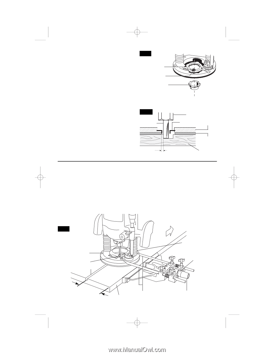
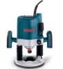
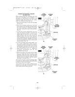
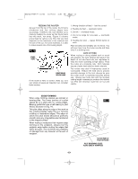
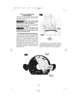
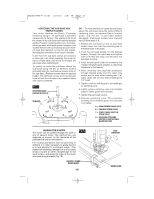
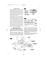
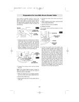
BM2610995777 10/03 10/7/03 4:51 PM Page 16 TEMPLET GUIDES The router is equipped with an exclusive quickchange templet guide adapter, which firmly grips the guides with a spring-loaded ring. To insert or change the templet guide, retract the templet guide release lever. Align the cutaways on the templet guide with the tabs on the bottom of the templet guide adapter. Insert the templet guide and release the lever to grip the templet guide in place (Fig. 19). Templet guides are used with a number of special accessories, such as hinge templets, which are listed in your BOSCH catalog. In addition, special templets are easily prepared for cutting repeated patterns, special designs, inlays, and other applications. A templet pattern may be made of plywood, hardboard, metal or even plastic, and the design can be cut with a router, jigsaw, or other suitable cutting tool. Remember that the pattern will have to be made to compensate for the distance between the router bit and the templet guide (the "offset"), as the final workpiece will differ in size from the templet pattern by that amount, due to the bit position (Fig. 20). FIG. 19 TEMPLET GUIDE ADAPTER TEMPLET GUIDE RELEASE LEVER TEMPLET GUIDE (optional accessory) FIG. 20 ROUTER BIT OFFSET COLLET CHUCK TEMPLET GUIDE ROUTER SUB-BASE TEMPLET PATTERN WORKPIECE DELUXE ROUTER GUIDE (Not included, available as accessory) The Bosch deluxe router guide is an optional accessory that will guide the router parallel to a straight edge or allow you to create circles and arcs. The deluxe router guide is supplied with two rods and six thumb screws to fasten the guide (Fig. 21). In addition, it features a fine adjustment knob and indicator for accurately positioning the edge guide relative to the bit. With the guide installed and adjusted, the router should be fed normally, keeping the guide in contact with the edge of the workpiece at all times. The deluxe router guide may also be positioned directly under the router base for operations where a cut is needed close to or at the edge of the work. For complete instructions on installation and operation, please refer to the instructions which are included with this accessory. FIG. 21 FEED DIRECTION BASE THUMB SCREW CUT THUMB SCREW (BEHIND POST) FINE ADJUSTMENT INDICATOR DESIRED WIDTH WORKPIECE ROUTER GUIDE RODS -16- FINE ADJUSTMENT KNOB
-
 1
1 -
2
-
3
-
4
-
5
-
6
-
7
-
8
-
9
-
10
-
 11
11 -
 12
12 -
 13
13 -
 14
14 -
 15
15 -
 16
16 -
 17
17 -
 18
18 -
 19
19 -
 20
20 -
 21
21 -
22
-
23
-
24
-
25
-
26
-
27
-
28
-
29
-
30
-
31
-
32
-
33
-
34
-
35
-
36
-
37
-
38
-
39
-
40
-
41
-
42
-
43
-
44
-
45
-
46
-
47
-
48
-
49
-
50
-
51
-
52
-
53
-
54
-
55
-
56
 |
 |