Bosch HMV9302 Service Manual - Page 26
Test And Checkout Procedures, And Trouble Shooting
 |
UPC - 825225830412
View all Bosch HMV9302 manuals
Add to My Manuals
Save this manual to your list of manuals |
Page 26 highlights
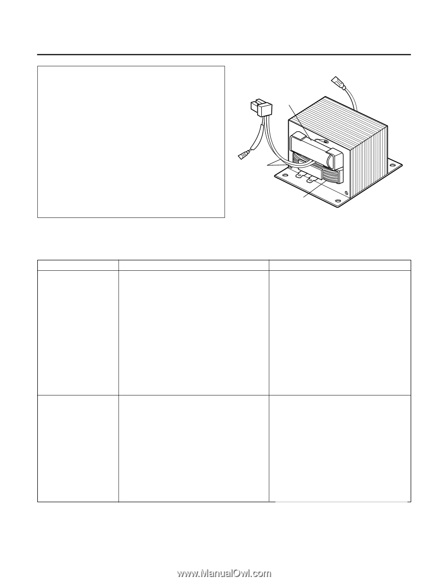
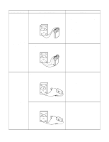
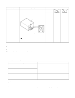
TEST AND CHECKOUT PROCEDURES, AND TROUBLE SHOOTING - CAUTIONS - - DISCONNECT THE POWER SUPPLY CORD FROM THE WALL OUTLET WHENEVER REMOVINGING THE CABINET FROM THE UNIT. PROCEED WITH THE TESTS ONLY AFTER DISCHARGING THE HIGH VOLTAGE CAPACITOR AND REMOVING THE WIRE LEADS FROM THE PRIMARY WINDING OF THE HIGH VOLTAGE TRANSFORMER. (SEE FIGURE 24) - ALL OPERATIONAL CHECKS WITH MICROWAVE ENERGY MUST BE DONE WITH A LOAD (1 LITER OF WATER IN CONTAINER) IN THE OVEN. Secondary Winding Filament Winding Primary Winding A. TEST PROCEDURES COMPONENTS TEST PROCEDURES 1) Measure the resistance: Across the filament terminals of the magnetron with an ohm-meter on Rx1 scale. Figure 24 RESULTS Normal reading: Less than 1 ohm. MAGNETRON (Wire leads are removed) 2) Measure the resistance: Between each filament terminal of the magnetron and the chassis ground with an ohm-mater on high test scale. Normal reading: Infinite ohms. NOTE: Replace the magnetron, if the magnetron checks and all of the high voltage component tests are good, but the unit still does not heat a load. HIGH-VOLTAGE TRANSFORMER (Wire leads are removed) 1) Measure the resistance: With an ohm-meter on Rx1 scale. a. Primary winding; b. Filament winding; c. Secondary winding; 2) Measure the resistance: With an ohm-meter on highest scale. a. Primary winding to ground; b. Filament winding to ground; Normal readings: Approx. 0.2 to 0.5 ohm. Less than 0.1 ohm. Approx. 50 to 120 ohms. Normal readings: Infinite ohms. Infinite ohms. NOTE: A MICROWAVE ENERGY LEAKAGE TEST MUST ALWAYS BE PERFORMED WHEN THE UNIT IS SERVICED FOR ANY REASON. 7-15
-
 1
1 -
2
-
3
-
4
-
5
-
6
-
7
-
8
-
9
-
10
-
11
-
12
-
13
-
14
-
15
-
16
-
17
-
18
-
19
-
20
-
 21
21 -
 22
22 -
 23
23 -
 24
24 -
 25
25 -
 26
26 -
 27
27 -
 28
28 -
 29
29 -
 30
30 -
 31
31 -
32
-
33
-
34
-
35
-
36
-
37
-
38
-
39
-
40
-
41
-
42
-
43
-
44
 |
 |