Bosch HMV9302 Service Manual - Page 33
Problem - C, Problem - D
 |
UPC - 825225830412
View all Bosch HMV9302 manuals
Add to My Manuals
Save this manual to your list of manuals |
Page 33 highlights
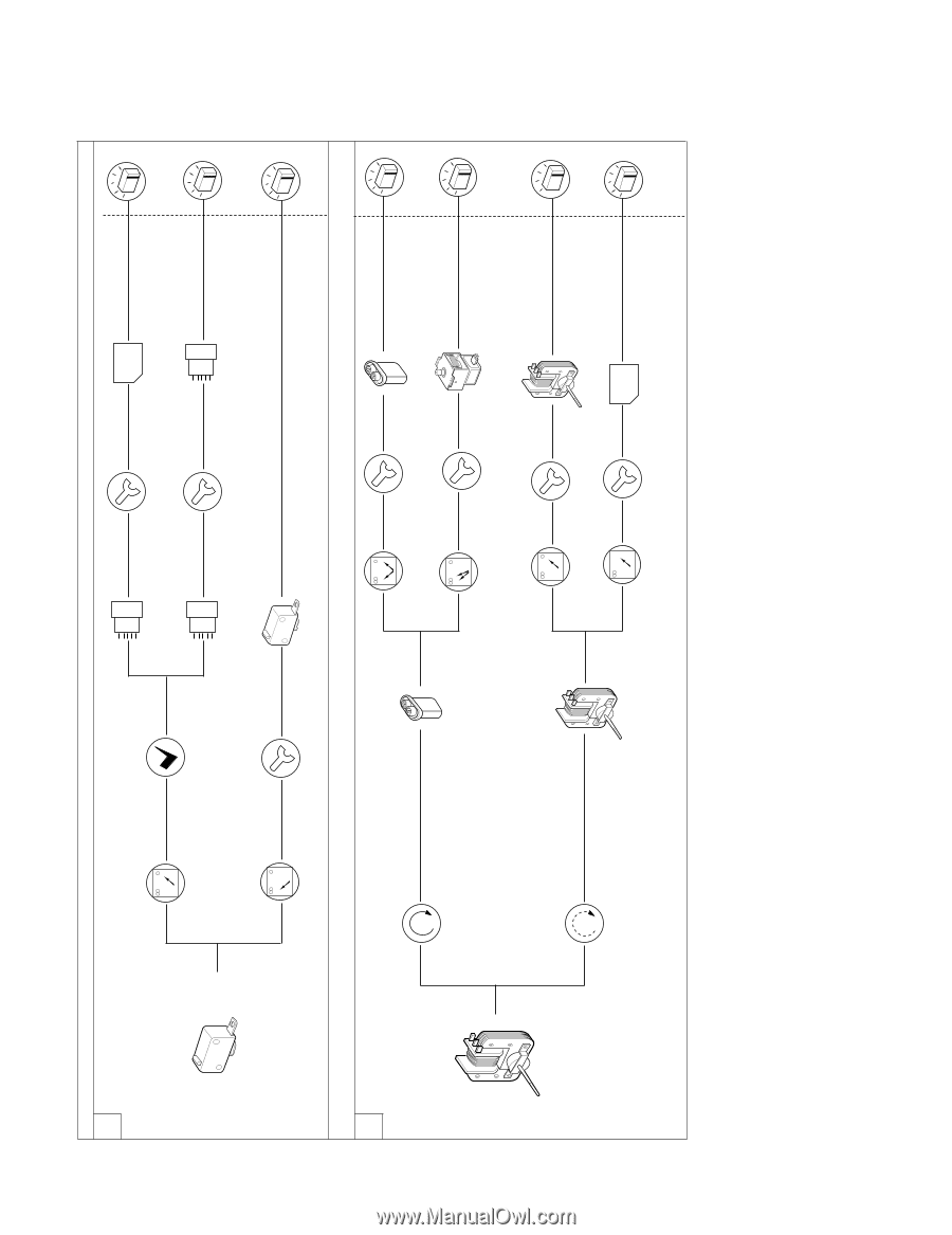
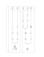
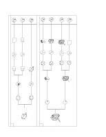
7-22 PROBLEM - C: Display does not start countdown when START key is touched. Check: 1. TOUCH KEY BOARD (START KEY FUNCTION) 1 Continuity OK Check continuity of connector CN2 between Pin 1(PK) and pin 3(BL) when the door is closed No continuity PROBLEM - D: Unit operation seems to be normal but little or no heating is produced in oven load. 1 Check: 1. AIR VENTS Normal operation Check contact of connector S1 Contact OK Poor contact Adjust or replace door sensing switch. Normal Primary switch Replace Circuit board Correct seating Measure resistance of H.V.capacitor (see page 7-16) Resistance incorrect Replace H.V.C. Normal resistance Replace magnetron Normal circuit board Normal contact Normal H.V.C. Normal magnetron Check operation of fan motor when START key is touched. No operation Measure resistance of fan motor Terminal A~C: 140 to 150 ohm Terminal A~B: 25 to 40 ohm Resistance incorrect 33 Normal resistance Replace fan motor Normal fan motor Replace circuit board Normal circuit board Runs Runs Runs Runs Runs Runs Runs
-
 1
1 -
2
-
3
-
4
-
5
-
6
-
7
-
8
-
9
-
10
-
11
-
12
-
13
-
14
-
15
-
16
-
17
-
18
-
19
-
20
-
21
-
22
-
23
-
24
-
25
-
26
-
27
-
 28
28 -
 29
29 -
 30
30 -
 31
31 -
 32
32 -
 33
33 -
 34
34 -
 35
35 -
 36
36 -
 37
37 -
 38
38 -
39
-
40
-
41
-
42
-
43
-
44
 |
 |