Bosch HMV9302 Service Manual - Page 32
Problem - A, Problem - B, Trouble Shooting
 |
UPC - 825225830412
View all Bosch HMV9302 manuals
Add to My Manuals
Save this manual to your list of manuals |
Page 32 highlights
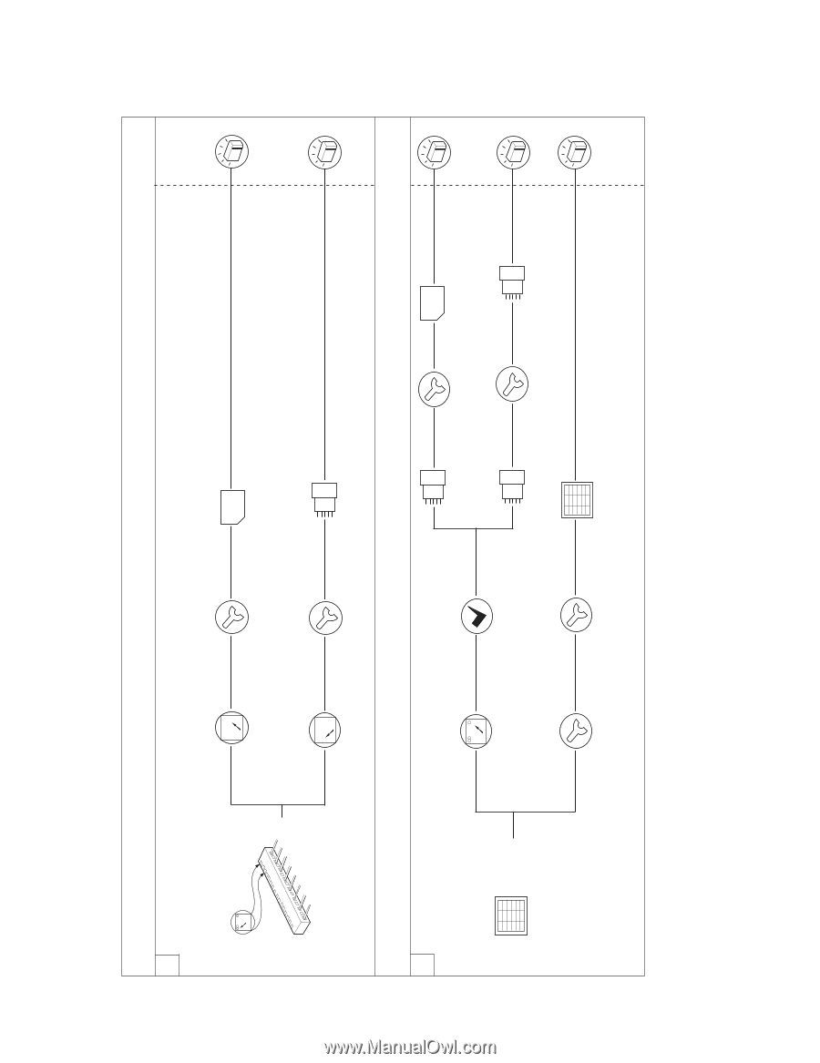
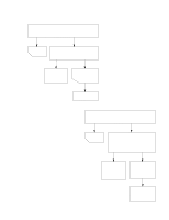
C. TROUBLE SHOOTING Before following this troubleshooting read TRIAL OPERATION on page 6-1. ¥ DISPLAY Problems, A thru C ¥ HELP UP Problems, D thru E ¥ BUZZER Problems, F PROBLEM - A: PLEASE SET TIME OF DAY does not appear in display window when power supply cord is plugged into wall outlet. 1 Check: 1. POWER SUPPLY 2. FUSE (See CHECKOUT PROCEDURES FOR FUSE BLOWING: on page 7-18) 3. OVEN CAVITY THERMOSTAT 7-21 0 120 120V Replace Normal Runs circuit board circuit board WH RD 0 120 Measure voltage between pin 1 and pin 3 of connector CN1. Voltage Correct Normal Runs incorrect connections resistance PROBLEM - B: Display does not show correct numbers and/or correct indications when programmed. 1 Contact Replace Normal Runs ok circuit board circuit board Normal resistance Check contact of connector S1 Poor Correct Normal Runs contact seating contact Measure resistance of touch key board after removing connector S1. (See page 7-4 and 7-17) Runs Resistance incorrect Replace touch key board. Normal touch key board
-
 1
1 -
2
-
3
-
4
-
5
-
6
-
7
-
8
-
9
-
10
-
11
-
12
-
13
-
14
-
15
-
16
-
17
-
18
-
19
-
20
-
21
-
22
-
23
-
24
-
25
-
26
-
 27
27 -
 28
28 -
 29
29 -
 30
30 -
 31
31 -
 32
32 -
 33
33 -
 34
34 -
 35
35 -
 36
36 -
 37
37 -
38
-
39
-
40
-
41
-
42
-
43
-
44
 |
 |