Bosch HMV9302 Service Manual - Page 29
Checkout Procedures
 |
UPC - 825225830412
View all Bosch HMV9302 manuals
Add to My Manuals
Save this manual to your list of manuals |
Page 29 highlights
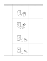
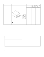
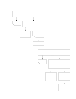
COMPONENTS RELAY2 TEST PROCEDURES Check for continuity of relay 2 with an ohm-meter. (Remove wire leads from relay 2 and operate the unit.) Relay 2 Figure 32 CAUTION : The relay connector 2 must be correctly connected Relay 2. POWER LEVEL 1 2 3 4 5 6 7 8 9 10 RESULTS 4 sec 6 sec 8 sec 10 sec 12 sec 14 sec 16 sec 18 sec 20 sec 22 sec 18 sec 16 sec 14 sec 12 sec 10 sec 8 sec 6 sec 4 sec 2 sec 0 NOTES: • A MICROWAVE ENERGY TEST MUST ALWAYS BE PERFORMED WHEN THE UNIT IS SERVICED FOR ANY REASON. • MAKE SURE THE WIRE LEADS ARE IN THE CORRECT POSITION. • WHEN REMOVING THE WIRE LEADS FROM THE PARTS, BE SURE TO GRASP THE CONNECTOR, NOT THE WIRES. B. CHECKOUT PROCEDURES (1) CHECKOUT PROCEDURES FOR FUSE BLOWING CAUTION: REPLACE BLOWN FUSE WITH 20 AMPERE FUSE. PROBLEMS CAUSES Fuse blows immediately after the door is closed. Fuse blows immediately after the door is opened. Improper operation of the primary interlock, secondary interlock switches and/or the interlock monitor switch. Fuse blows when the door is closed and START key is touched. Malfunction of the high voltage transformer; the high voltage capacitor including the diode, the magnetron, the blower motor or the circuit board. NOTES: • If the fuse is blown by an improper switch operation, replace the all Interlock switches, PCB Ass'y and the fuse at the same time. After replacing the the all Interlock switches, PCB Ass'y,Fuse with new ones, make sure that they are correctly connected. • Check for microwave energy leakage according to INTERLOCK ADJUSTMENT PROCEDURES on page 7-12 when the primary interlock, secondary interlock switches and/or the interlock monitor switches are adjusted or replaced. 7-18
-
 1
1 -
2
-
3
-
4
-
5
-
6
-
7
-
8
-
9
-
10
-
11
-
12
-
13
-
14
-
15
-
16
-
17
-
18
-
19
-
20
-
21
-
22
-
23
-
 24
24 -
 25
25 -
 26
26 -
 27
27 -
 28
28 -
 29
29 -
 30
30 -
 31
31 -
 32
32 -
 33
33 -
 34
34 -
35
-
36
-
37
-
38
-
39
-
40
-
41
-
42
-
43
-
44
 |
 |