Cisco AIR-CB21AG-A-K9 Quick Start Guide - Page 14

Known, Known Issues, Issues, Issues Related to, Related to, Related to LAN, LANPlanner, Planner, - driver software

Page 14 highlights

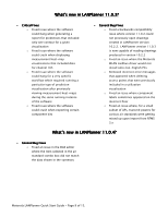
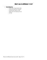
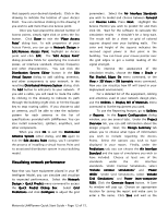
Known Issues Related to LANPlanner 11.0 • Compatibility with previous Motorola PC-based software versions: LANPlanner 11.0 is backwards compatible with drawings created in LANPlanner 10.x. However, grid predictions created in LANPlanner 10.x will not be correctly colored in LANPlanner 11.0. All grid predictions previously calculated using LANPlanner 10.x must be recalculated and redisplayed in LANPlanner 11.0. Note that LANPlanner 10.x cannot open drawings created with version 11.0 or higher. • LANPlanner 11.0 comes with new default color schemes that increase the maximum data rate visible in performance visualizations to values that coincide with the 802.11n standard. To visualize the new data rates of 802.11n without additional modification, these new color schemes will need to be loaded manually for existing drawings created before version 11.0 (or EnterprisePlanner 11.0/ SiteScanner 2.0). To load the new color schemes: 1. Open your drawing 2. Select Utilities->Edit Color Schemes... from the menu 3. Click the Load From File button at the bottom of the Edit Colors dialog 4. Open the C:\Program Files\LANPlanner\BOM\colors.xml file to load the new default color schemes into your drawing • When visualizing 802.11n performance for 40MHz channels it may be necessary to configure the color scheme for your visualization to include higher data rates than the default 130Mbps. A suggested scheme has already been provided for this. To assign the Peak Data Rate (up to 300Mbps) scheme: 1. Open your drawing 2. Select Utilities->Edit Color Schemes... from the menu 3. Select the data rate display type you would like to change from the Color Scheme Assignment list (Contour Data Rate, Grid Data Rate, etc.) 4. Click the Edit button in the Color Scheme Assignment section of the dialog 5. Select the Peak Data Rate (up to 300Mbps) color scheme • Some Optimatic features may on occasion become disabled after visualizing measurement heat-maps. Work-a-round: Select another menu item prior to selecting an optimization menu item (e.g. Record Measurements). The software will then function as intended. • Conflict with TrendMicro firewall: TrendMicro firewall must be disabled before taking measurements in RF Monitoring mode with the custom driver to avoid possible system crashes. The following steps can be taken to disable the firewall: 1. Go to Start -> Run -> services.msc 2. Double click the service named OfficeScanNT Personal firewall 3. In the dialog that appears change the Startup type to Disabled, press Stop and click Ok 4. Go to Start -> Control Panel -> Network Connections 5. Right click the Motorola measurements adapter and select Properties 6. In the dialog that appears uncheck the Trend Micro Common Firewall Driver in the list of available network components and press OK Motorola LANPlanner Quick Start Guide - Page 14 of 15.

  • 1
  • 2
  • 3
  • 4
  • 5
  • 6
  • 7
  • 8
  • 9
  • 10
  • 11
  • 12
  • 13
  • 14
  • 15

Motorola LANPlanner Quick Start Guide - Page 14 of 15.
Known
Known
Known
Known Issues
Issues
Issues
Issues Related to
Related to
Related to
Related to LAN
LAN
LAN
LANPlanner
Planner
Planner
Planner 11
11
11
11.0
Compatibility with previous
Compatibility with previous Motorola
Motorola
Motorola
Motorola PC
PC
PC
PC-based
based
based
based
software versions:
software versions:
software versions:
software versions: LANPlanner 11.0 is
backwards compatible with drawings created in
LANPlanner 10.x.
However, grid predictions
created in LANPlanner 10.x will not be correctly
colored in LANPlanner 11.0. All grid predictions
previously calculated using LANPlanner 10.x
must be recalculated and redisplayed in
LANPlanner 11.0. Note that LANPlanner 10.x
cannot
open drawings created with version
11.0 or higher.
LANPlanner 11.0 comes with new default color
schemes that increase the maximum data rate
visible in performance visualizations to values
that coincide with the 802.11n standard.
To
visualize the new data rates of 802.11n without
additional modification, these new color
schemes will need to be loaded manually for
existing drawings created before version 11.0
(or EnterprisePlanner 11.0/ SiteScanner
2.0).
To load the new color schemes:
1.
Open your drawing
2.
Select Uti
Uti
Uti
Utilities
lities
lities
lities->Edit Color Schemes...
>Edit Color Schemes...
from the menu
3.
Click the Load From File
Load From File
Load From File
Load From File button at the
bottom of the Edit Colors
Edit Colors
Edit Colors
Edit Colors dialog
4.
Open the C:
C:
C:
C:\Program
Program
Program
Program
Files
Files
Files
Files\LAN
LAN
LAN
LANPlanner
Planner
Planner
Planner\BOM
BOM
BOM
BOM\colors.xml
colors.xml
colors.xml
colors.xml file
to load the new default color schemes
into your drawing
When visualizing 802.11n performance for
40MHz channels it may be necessary to
configure the color scheme for your
visualization to include higher data rates than
the default 130Mbps.
A suggested scheme has
already been provided for this.
To assign the
Peak Data Rate (up to 300
Peak Data Rate (up to 300Mbps)
Mbps)
Mbps)
Mbps) scheme:
1.
Open your drawing
2.
Select Utilities
Utilities
Utilities
Utilities->Edit Color Schemes...
>Edit Color Schemes...
from the menu
3.
Select the data rate display type you
would like to change from the Color
Color
Color
Color
Scheme Assignment
Scheme Assignment
Scheme Assignment
Scheme Assignment list (Contour Data
Rate, Grid Data Rate, etc.)
4.
Click the Edit
Edit
Edit
Edit button in the Color
Color
Color
Color
Scheme Assignment
Scheme Assignment
Scheme Assignment
Scheme Assignment section of the
dialog
5.
Select the Peak Data Rate (up to
Peak Data Rate (up to
300Mbps)
300Mbps)
300Mbps)
300Mbps) color scheme
Some Optimatic features may on occasion
become disabled after visualizing
measurement heat-maps.
Work-a-round:
Select another menu item prior to selecting an
optimization menu item (e.g. Record
Measurements).
The software will then
function as intended.
Conflict with TrendMicro firewall:
Conflict with TrendMicro firewall: TrendMicro
firewall must be disabled before taking
measurements in RF Monitoring mode with the
custom driver to avoid possible system
crashes. The following steps can be taken to
disable the firewall:
1.
Go to Start -> Run -> services.msc
2.
Double click the service named
OfficeScanNT Personal firewall
3.
In the dialog that appears change the
Startup type
Startup type
Startup type
Startup type to Disabled
Disabled
Disabled
Disabled, press Stop
Stop
Stop
Stop and
click Ok
Ok
Ok
Ok
4.
Go to Start -> Control Panel -> Network
Connections
5.
Right click the Motorola measurements
adapter and select Properties
Properties
Properties
Properties
6.
In the dialog that appears uncheck the
Trend Micro Common Firewall Driver
Trend Micro Common Firewall Driver in the
list of available network components and
press OK
OK
OK
OK