Compaq Presario 1000 HP Compaq Business Notebook nx7000/Compaq Presario Widesc - Page 126
Slide the system board to the right an angle, Remove the system board.
 |
View all Compaq Presario 1000 manuals
Add to My Manuals
Save this manual to your list of manuals |
Page 126 highlights
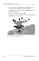
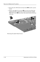
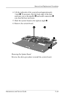
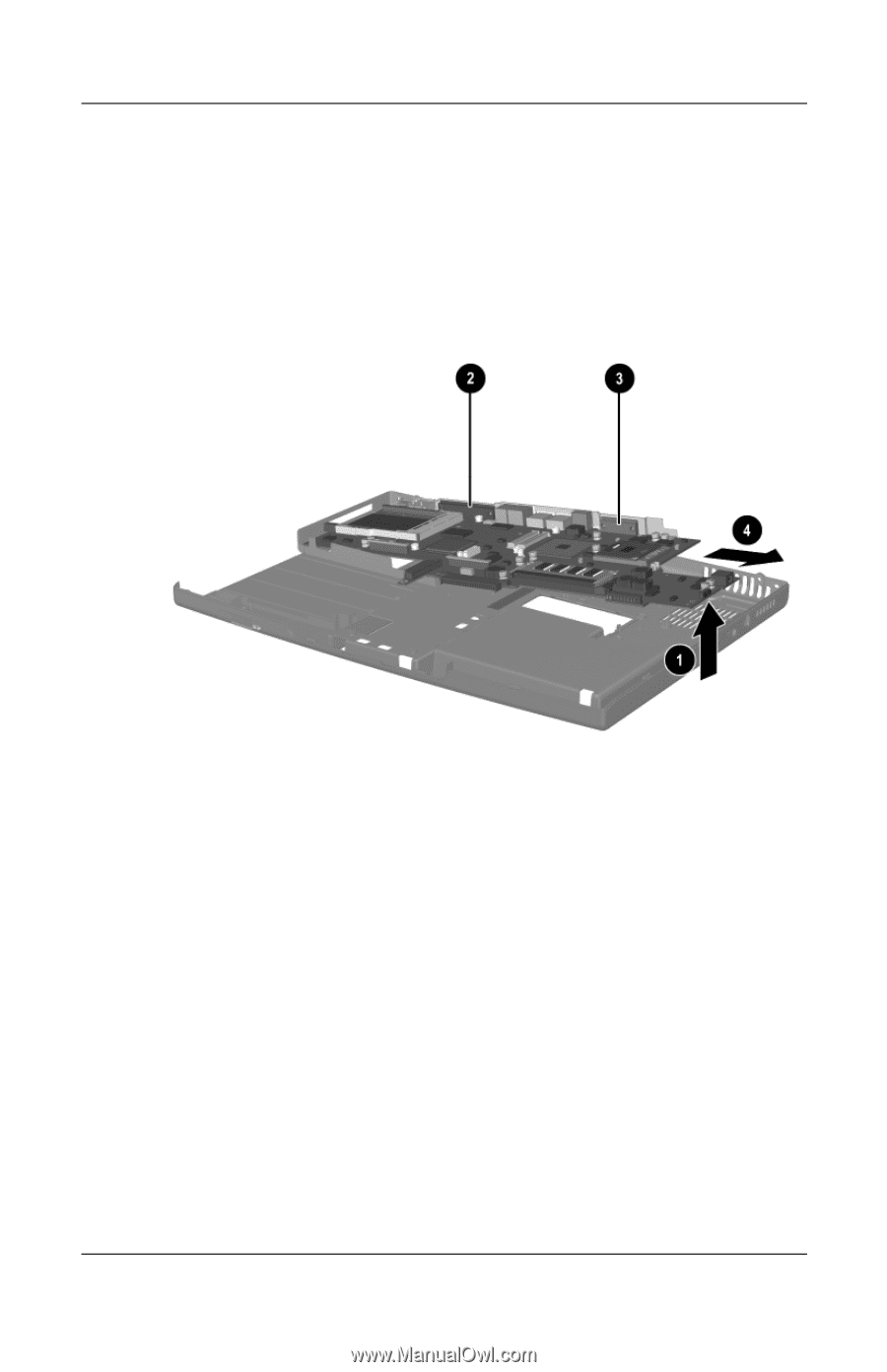
Removal and Replacement Procedures 4. Lift the right side of the system board approximately 1 inch 1. If necessary, flex the back edge of the base enclosure out so the parallel 2 and serial connectors 3 can clear the base enclosure. 5. Slide the system board to the right an angle 4. 6. Remove the system board. Removing the System Board Reverse the above procedure to install the system board. Maintenance and Service Guide 5-43
-
 1
1 -
2
-
3
-
4
-
5
-
6
-
7
-
8
-
9
-
10
-
11
-
12
-
13
-
14
-
15
-
16
-
17
-
18
-
19
-
20
-
21
-
22
-
23
-
24
-
25
-
26
-
27
-
28
-
29
-
30
-
31
-
32
-
33
-
34
-
35
-
36
-
37
-
38
-
39
-
40
-
41
-
42
-
43
-
44
-
45
-
46
-
47
-
48
-
49
-
50
-
51
-
52
-
53
-
54
-
55
-
56
-
57
-
58
-
59
-
60
-
61
-
62
-
63
-
64
-
65
-
66
-
67
-
68
-
69
-
70
-
71
-
72
-
73
-
74
-
75
-
76
-
77
-
78
-
79
-
80
-
81
-
82
-
83
-
84
-
85
-
86
-
87
-
88
-
89
-
90
-
91
-
92
-
93
-
94
-
95
-
96
-
97
-
98
-
99
-
100
-
101
-
102
-
103
-
104
-
105
-
106
-
107
-
108
-
109
-
110
-
111
-
112
-
113
-
114
-
115
-
116
-
117
-
118
-
119
-
120
-
 121
121 -
 122
122 -
 123
123 -
 124
124 -
 125
125 -
 126
126 -
 127
127 -
 128
128 -
 129
129 -
 130
130 -
 131
131 -
132
-
133
-
134
-
135
-
136
-
137
-
138
-
139
-
140
-
141
-
142
-
143
-
144
-
145
-
146
-
147
-
148
-
149
-
150
-
151
-
152
-
153
-
154
-
155
-
156
-
157
-
158
-
159
-
160
-
161
-
162
-
163
-
164
-
165
-
166
-
167
-
168
-
169
-
170
-
171
-
172
-
173
-
174
 |
 |
Removal and Replacement Procedures
Maintenance and Service Guide
5–43
4. Lift the right side of the system board approximately
1 inch
1
. If necessary, flex the back edge of the base
enclosure out so the parallel
2
and serial connectors
3
can clear the base enclosure.
5. Slide the system board to the right an angle
4
.
6. Remove the system board.
Removing the System Board
Reverse the above procedure to install the system board.