Compaq nc6000 HP Compaq nc6000 Notebook PC - Maintenance and Service Guide - Page 118
Fan Assembly
 |
View all Compaq nc6000 manuals
Add to My Manuals
Save this manual to your list of manuals |
Page 118 highlights
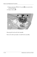
Removal and Replacement Procedures 5.15 Fan Assembly Fan assembly Spare Part Number Information 345065-001 1. Prepare the notebook for disassembly (refer to Section 5.3). 2. Remove the keyboard (refer to Section 5.9). 3. Remove the switch cover (refer to Section 5.12). 4. Remove the keyboard plate (refer to Section 5.13). 5. Disconnect the fan cable 1 from the system board. 6. Remove the T8M2.5×7.0 2 and T8M2.5×5.0 screws 3 that secure the fan assembly to the notebook. Removing the Fan Assembly Screws 5-32 Maintenance and Service Guide
-
 1
1 -
2
-
3
-
4
-
5
-
6
-
7
-
8
-
9
-
10
-
11
-
12
-
13
-
14
-
15
-
16
-
17
-
18
-
19
-
20
-
21
-
22
-
23
-
24
-
25
-
26
-
27
-
28
-
29
-
30
-
31
-
32
-
33
-
34
-
35
-
36
-
37
-
38
-
39
-
40
-
41
-
42
-
43
-
44
-
45
-
46
-
47
-
48
-
49
-
50
-
51
-
52
-
53
-
54
-
55
-
56
-
57
-
58
-
59
-
60
-
61
-
62
-
63
-
64
-
65
-
66
-
67
-
68
-
69
-
70
-
71
-
72
-
73
-
74
-
75
-
76
-
77
-
78
-
79
-
80
-
81
-
82
-
83
-
84
-
85
-
86
-
87
-
88
-
89
-
90
-
91
-
92
-
93
-
94
-
95
-
96
-
97
-
98
-
99
-
100
-
101
-
102
-
103
-
104
-
105
-
106
-
107
-
108
-
109
-
110
-
111
-
112
-
 113
113 -
 114
114 -
 115
115 -
 116
116 -
 117
117 -
 118
118 -
 119
119 -
 120
120 -
 121
121 -
 122
122 -
 123
123 -
124
-
125
-
126
-
127
-
128
-
129
-
130
-
131
-
132
-
133
-
134
-
135
-
136
-
137
-
138
-
139
-
140
-
141
-
142
-
143
-
144
-
145
-
146
-
147
-
148
-
149
-
150
-
151
-
152
-
153
-
154
-
155
-
156
-
157
-
158
-
159
-
160
-
161
-
162
-
163
-
164
-
165
-
166
-
167
-
168
-
169
-
170
-
171
-
172
-
173
-
174
-
175
-
176
-
177
-
178
-
179
-
180
-
181
-
182
-
183
-
184
-
185
-
186
-
187
-
188
-
189
-
190
-
191
-
192
-
193
-
194
-
195
-
196
 |
 |

5–32
Maintenance and Service Guide
Removal and Replacement Procedures
5.15
Fan Assembly
1. Prepare the notebook for disassembly (refer to
Section 5.3
).
2. Remove the keyboard (refer to
Section 5.9
).
3. Remove the switch cover (refer to
Section 5.12
).
4. Remove the keyboard plate (refer to
Section 5.13
).
5. Disconnect the fan cable
1
from the system board.
6. Remove the T8M2.5×7.0
2
and T8M2.5×5.0 screws
3
that
secure the fan assembly to the notebook.
Removing the Fan Assembly Screws
Spare Part Number Information
Fan assembly
345065-001