Craftsman 30084N Operation Manual
Craftsman 30084N - 180 Amp 220 Volt Digital MIG Welder Manual
 |
UPC - 055249070420
View all Craftsman 30084N manuals
Add to My Manuals
Save this manual to your list of manuals |
Craftsman 30084N manual content summary:
- Craftsman 30084N | Operation Manual - Page 1
No. 117.205710 CAUTION: Before using welder, read this manual and follow all its Safety Rules and Operating Instructions. w Safety Rules w Installation w Operation w Maintenance w Parts w Español Sears, Roebuck and Co., Hoffman Estates, IL 60179 U.S.A. Visit the Craftsman web page: www.sears.com - Craftsman 30084N | Operation Manual - Page 2
according to the owner's manual instructions, if the welder fails due to a defect in material or workmanship, Sears will repair or replace the welder free of charge. This warranty does not cover the welding gun, cables, or normal consumable parts. WARRANTY SERVICE IS AVAILABLE BY SIMPLY CONTACTING - Craftsman 30084N | Operation Manual - Page 3
Hub Tension 9 2-10. Changing Input Voltage 9 2-11. Electrical Service Guide 10 2-12. Selecting A Location And Connecting Input Power 10 2- Wire Guide 15 4-4. Cleaning Or Replacing Gun Liner 16 4-5. Replacing Switch And/Or Head Tube 17 4-6. Replacing Gun Contact Tip 18 4-7. Troubleshooting 18 - Craftsman 30084N | Operation Manual - Page 4
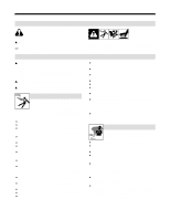
PARTS hazards. Consult symbols and related instructions below for necessary actions to avoid the hazards. 1-2. Arc Welding Hazards Y The symbols shown below are used throughout this manual engine before installing or servicing this equipment. Lockout wearing an air-supplied respirator. The coatings and - Craftsman 30084N | Operation Manual - Page 5
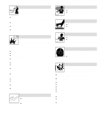
air-supplied respirator. HOT PARTS can cause severe burns. D Do not touch hot parts parts in good condition. D Turn face away from valve outlet when opening cylinder valve. D Keep protective cap in place over valve except when cylinder is in use or connected for use. D Read and follow instructions - Craftsman 30084N | Operation Manual - Page 6
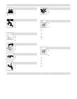
from moving parts such as fans. D Keep all doors, panels, covers, and guards closed and securely in place. FALLING UNIT can cause injury. D Use lifting eye to lift unit only, NOT running gear, gas cylinders, or any other accessories. D Use equipment of adequate capacity to lift and support unit - Craftsman 30084N | Operation Manual - Page 7
1-5. EMF Information Considerations About Welding And The Effects Of Low Frequency Electric And Magnetic Fields Welding current, as it flows through welding cables, will cause electromagnetic fields. There has been and still is some concern about such fields. However, after examining more than 500 - Craftsman 30084N | Operation Manual - Page 8
SECTION 2 - INSTALLATION 2-1. Specifications Rated Welding Output Amperage Range 150 A @ 23 Volts DC, 60% Duty Cycle 30 - 185 Maximum Open-Circuit Voltage DC Amperes Input at Rated Load Output, 60 Hz, Single-Phase 200 V 230 V KVA Weight KW 33 30 (1.6)* 26 (1.4)* 6 (0.27)* 5 (0.13)* 165 - Craftsman 30084N | Operation Manual - Page 9
Cycle And Overheating Duty Cycle is percentage of 10 minutes that unit can weld at rated load without overheating. If unit overheats, thermostat(s) opens, output stops, and cooling fan runs. Wait fifteen minutes for unit to cool. Reduce amperage or voltage, or duty cycle before welding. Y Exceeding - Craftsman 30084N | Operation Manual - Page 10
in 4 7 5 6 Tools Needed: 1/2, 3/4 in ST-801 566-A OR 8 1 2 3 Argon Gas 1 2 3 9 CO2 Gas Obtain gas cylinder and chain to running gear, wall, or other stationary support so cylinder cannot fall and break off valve. 1 Cap 2 Cylinder Valve Remove cap, stand to side of valve, and open valve slightly - Craftsman 30084N | Operation Manual - Page 11
opening until it bottoms against drive assembly. Tighten nut. 4 Gun Trigger Plug Insert plug into receptacle, and tighten threaded collar. Close door . 2-8. Setting Gun Polarity Ref. ST-801 567 1 Polarity Changeover Label Always read and follow manufacture's recommended polarity. 1 Tools - Craftsman 30084N | Operation Manual - Page 12
2-9. Installing Wire Spool And Adjusting Hub Tension Use compression spring with 8 in (200 mm) spools. Tools Needed: 15/16 in 2-10. Changing Input Voltage 2 3 When a slight force is needed to turn spool, tension is set. ST-072573-B Y Turn Off unit, and - Craftsman 30084N | Operation Manual - Page 13
2-11. Electrical Service Guide Input Voltage 200 230 Input Amperes At Rated Output 30 26 Max Recommended Standard Fuse Or Circuit Breaker Rating In Amperes Circuit Breaker 1, Time-Delay 2 - Craftsman 30084N | Operation Manual - Page 14
2-13. Threading Welding Wire Tools Needed: Open pressure assembly. 4 in (102 mm) 6 in (150 mm) Pull and hold wire; cut off end. Push wire thru guides into gun; continue to hold wire. enough to prevent slipping. Cut off wire. Close and latch door. Ref. ST-801 570-A / ST-801 083 / S-0627-A - Craftsman 30084N | Operation Manual - Page 15
2-14. Weld Parameter Wire Type, Shielding Gas, And Flow Rate Wire Diameter (inch) Operator Controls Material Thickness 3/8 in (9.5 mm) 1/4 in 3/16 in 1/8 in (6.4 (4.8 (3.2 mm) mm) mm) 12 ga 14 ga 16 ga 18 ga 20 ga 22 ga Voltage Tap - - 6 5 4 3 3 2 2 1 1 .023 Wire Speed - - - Craftsman 30084N | Operation Manual - Page 16
2-15. Aluminum Weld Parameter For Use With Optional Spool Gun Wire Type, Shielding Gas, And Flow Rate Wire Diameter (inch) Operator Controls Material Thickness 3/8 in (9.5 mm) 1/4 in (6.4 mm) 3/16 in (4.8 m m) 1/8 in (3.2 mm) Voltage Tap 5 5 4 3 .030 4043 AL 100% Argon Wire Speed 88 - Craftsman 30084N | Operation Manual - Page 17
SECTION 3 - OPERATION 3-1. Front Panel Controls Controls For Standard Units 1 Wire Speed Control Use control to select a wire feed speed. Scale around control is not actual wire feed speed, but is for reference only. 2 Voltage Switch The higher the selected number, the thicker the material that - Craftsman 30084N | Operation Manual - Page 18
SECTION 4 - MAINTENANCE & TROUBLESHOOTING 4-1. Routine Maintenance Y Disconnect power before maintaining. circuit from overload. If CB1 opens, weld output stops. Press button to reset circuit breaker. Close door. 4-3. Changing Drive Roll And Inlet Wire Guide Tools Needed: 1 2 OM-194 199 - Craftsman 30084N | Operation Manual - Page 19
. 3/8 in Head Tube Remove nozzle, contact tip, and adapter. Tools Needed: 3/8 in Lay gun cable out straight before installing new liner Blow out gun casing. To Reassemble Gun: Insert new liner. Install and tighten wire outlet guide. Cut liner off 3/4 in (20 mm) (3/8 in [9.5 mm] for aluminum) - Craftsman 30084N | Operation Manual - Page 20
. 7 Place head tube in vice and tighten until nuts are tight. 8 Remove from vice. Reposition handle and install switch housing. Secure with handle locking nut. Tools Needed: 3/4 in OM-194 199 Page 17 Ref. ST-800 795-C - Craftsman 30084N | Operation Manual - Page 21
4-6. Replacing Gun Contact Tip Tools Needed: 4-7. Troubleshooting Y Turn Off unit. 1 Nozzle 2 Contact Tip Cut off welding wire at contact tip. Remove nozzle. Remove contact tip and install new contact tip. Reinstall nozzle. 2 1 Ref. 800 797-C Welding Trouble No weld output; wire does not feed. No - Craftsman 30084N | Operation Manual - Page 22
SECTION 5 - ELECTRICAL DIAGRAM OM-194 199 Page 19 Figure 5-1. Circuit Diagram SB-186 065 - Craftsman 30084N | Operation Manual - Page 23
SECTION 6 - MIG WELDING (GMAW) GUIDELINES 6-1. Typical MIG Process Connections Regulator/ Flowmeter Y Weld current can damage electronic parts in vehicles. Disconnect both battery cables before welding on a vehicle. Place work clamp as close to the weld as possible. Shielding Gas Wire Feeder/ - Craftsman 30084N | Operation Manual - Page 24
6-2. Typical MIG Process Control Settings NOTE These settings are guidelines only. Material and wire type, joint design, fitup, position, shielding gas, etc. affect settings. Test welds to be sure they comply to specifications. Material thickness determines weld parameters. 1/8 or .125 in .035 - Craftsman 30084N | Operation Manual - Page 25
6-3. Holding And Positioning Welding Gun NOTE Welding wire is energized when gun trigger is pressed. Before lowering helmet and pressing trigger, be sure wire is no more than 1/2 in (13 mm) past end of nozzle, and tip of wire is positioned correctly on seam. 1 3 2 5 1 Hold Gun and Control Gun - Craftsman 30084N | Operation Manual - Page 26
6-4. Conditions That Affect Weld Bead Shape NOTE Weld bead shape depends on gun angle, direction of travel, electrode extension (stickout), travel speed, thickness of base metal, wire feed speed (weld current), and voltage. 10° Push 10° Perpendicular Drag GUN ANGLES AND WELD BEAD PROFILES - Craftsman 30084N | Operation Manual - Page 27
6-5. Gun Movement During Welding NOTE Normally, a single stringer bead is satisfactory for most narrow groove weld joints; however, for wide groove weld joints or bridging across gaps, a weave bead or multiple stringer beads works better. 1 2 3 1 Stringer Bead - Steady Movement Along Seam 2 - Craftsman 30084N | Operation Manual - Page 28
extends too far out of nozzle. Be sure welding wire extends not more than 1/2 in (13 mm) beyond nozzle. 6-10. Troubleshooting - Excessive Penetration Excessive Penetration Good Penetration Excessive Penetration - weld metal melting through base metal and hanging underneath weld. Possible Causes - Craftsman 30084N | Operation Manual - Page 29
walls when using weaving technique. Keep arc on leading edge of weld puddle. Use correct gun angle of 0 to 15 degrees. 6-13. Troubleshooting - Burn-Through Burn-Through - weld metal melting completely through base metal resulting in holes where no metal remains. Possible Causes Excessive heat - Craftsman 30084N | Operation Manual - Page 30
far out of nozzle. Be sure welding wire extends not more than 1/2 in (13 mm) beyond nozzle. Unsteady hand. Support hand on solid surface or use two hands. 6-15. Troubleshooting - Distortion Base metal moves in the direction of the weld bead. Distortion - contraction of weld metal during welding - Craftsman 30084N | Operation Manual - Page 31
6-16. Common MIG Shielding Gases This is a general chart for common gases and where they are used. Many different combinations (mixtures) of shielding gases have been developed over the years. The most commonly used shielding gases are listed in the following table. Gas Argon Argon + 25% CO2 CO2 - Craftsman 30084N | Operation Manual - Page 32
SECTION 7 - PARTS LIST-Welder Model No. 117.205710 . * Standard hardware item - may be purchased locally. 11 12 13 14 15 16 17 18 19 20 21 10 9 8 7 6 + - 5 - Craftsman 30084N | Operation Manual - Page 33
. GROMMET, SCR .250 panel hole 8 026 947 . . . . STAND-OFF 2 TP1 . . . 604 515 . . . . THERMOSTAT, NC open 211F 1 . . . 6 . . . . . FM . . . . 123 468 . . . . MOTOR, fan 230V 60/50 Hz 3000RPM Replacement Parts. Model number required when ordering parts from a Sears Parts/Repair Center. OM- - Craftsman 30084N | Operation Manual - Page 34
17 18 34 12 35 27 20 23 26 25 24 36 22 21 Figure 7-2. Center Baffle w/Components ST-801 631-D Item Dia. Part No. Mkgs. No. Description Figure 7-2. Baffle, Center w/Components (Fig 7-1 Item 4) Quantity . . . 1 058 427 . . RING, retaining spool 1 . . . 2 085 980 . . NUT, 625-11 .94 - Craftsman 30084N | Operation Manual - Page 35
Part No. Description Quantity Figure 7-2. Baffle, Center w/Components (Continued) (Fig 7-1 Item 4) . . . 15 083 147 . . . . GROMMET, scr No. 8/10 panel hole 4 . . . 16 180 927 . . REEL SUPPORT -20 x .750 4 196 894 . . BRACKET, consumable/tool tray 1 202 449 . . PLATE, switch 1 *Standard - Craftsman 30084N | Operation Manual - Page 36
7-3. M-15 Gun To maintain the factory original performance of your equipment, use only Manufacturer's Suggested Replacement Parts. Model number required when ordering parts from a Sears Parts /Repair Center. Item Part No. No. Description Quantity 169 589 Figure 7-3. M-15 Gun (Fig 7-1 Item 36 - Craftsman 30084N | Operation Manual - Page 37
. . SCREW 3 . . . 15 090 423 . . ROLL, drive V groove .023-.035 1 . . . 16 058 549 . . GUIDE, wire inlet 1/16 1 . . . 17 010 224 . . PIN, spring CS .187 x 1.000 1 . . . 18 SCREW, m Suggested Replacement Parts. Model number required when ordering parts from a Sears Parts /Repair Center. OM - Craftsman 30084N | Operation Manual - Page 38
Notes OM-194 199 Page 35 - Craftsman 30084N | Operation Manual - Page 39
Efectiva 1 enero, 2000 Garantía de un año para las antorchas o cables Craftsman. Por todo un año a partir de la fecha de compra, cuando se ha se ha mantenido la antorcha y los cables de acuerdo a las instrucciones del manual del operador. Si la antorcha o los cables fallan debido a un defecto en - Craftsman 30084N | Operation Manual - Page 40
ón 63 13-16. Gases Más Comunes para Protección de Soldadura MIG 64 Los terminos siguientes se usan de una forma intercambiable a lo largo de este manual: MIG = GMAW ADVERTENCIA Este producto cuando se usa para soldar o cortar, produce humo o gases que contienen químicos conocidos en el estado de - Craftsman 30084N | Operation Manual - Page 41
D Use equipo bien mantenido. Repare o reemplace partes dañadas inmediatamente.Mantenga la unidad de acuerdo al manual. D Use tirantes de seguridad para prevenir que soldadura. D Si la ventilación es mala, use un respirador de aire aprobado. D Lea las hojas de datos sobre seguridad de material (MSDS - Craftsman 30084N | Operation Manual - Page 42
cuando no lo use. D Siempre dé ventilación a espacios cerrados o use un respirador aprobado que reemplaza el aire. PARTES CALIENTES puedan causar quemaduras severas. D No toque a partes calientes sin guantes. D Deje enfriar a la antorcha o pistola antes de darle servicio. CAMPOS MAGNETICOS puede - Craftsman 30084N | Operation Manual - Page 43
de nuevo. D No bloquee o filtre el flujo de aire a la unidad. ELECTRICIDAD ESTATICA puede dañar a las circuito. PARTES QUE SE MUEVEN pueden causarle heridas. D Mantengase lejos de todas partes que esté instalada y aterrizada de acuerdo a este manual. D Si todavía ocurre interferencia, el operador - Craftsman 30084N | Operation Manual - Page 44
8-5. Información del EMF Consideración acerca de Soldadura y los Efectos de Campos Eléctricos y Magnéticos de Baja Frecuencia La corriente de soldadura cuando fluye por los cables de soldadura causará campos electromagnéticos. Ha habido una precupación acerca de estos campos. Sin embargo, después de - Craftsman 30084N | Operation Manual - Page 45
SECCION 9 - INSTALACION 9-1. Especificaciones Salida Nominal de Soldadura 150 Amps @ 23 VDC, 60% Ciclo de Trabajo Gama de Amperaje 30 - 185 Voltaje de Circuito Abierto Máximo (C.D.) Entrada en Amperios a la Carga Nominal, 60 Hz, Monofásica Peso 200 V 230 V KVA KW 33 30 (1,6)* 26 (1,4)* 6 - Craftsman 30084N | Operation Manual - Page 46
9-3. Ciclo de trabajo de la Fuente de Poder de Soldadura y el sobrecalentamiento Ciclo de Trabajo es un porcentaje de 10 minutos que la unidad o pistola puede soldar a la carga nominal sin sobrecalentarse. Si la unidad se sobrecaliente, el termostato se abre, salida se para, y el ventilador sigue - Craftsman 30084N | Operation Manual - Page 47
de la empuñadura de la grampa de trabajo y asegúrele en la parte superior de la grampa de trabajo con los herrajes. Cierre la puerta. ST-801 566 en el Regulador/ Flujómetro para la manguera de gas y la conexión en el parte trasero de la fuente de poder de soldar. 12 Ajuste del Flujo El flujo debe - Craftsman 30084N | Operation Manual - Page 48
9-7. Instalando la Pistola 1 2 3 4 1 Ensamblaje de los Rodillos de Alimentación 2 Perilla para Ajustar la Pistola 3 Extremo de la Pistola Afloje la perilla e inserte el extremo de la pistola a través del hueco hasta que se asiente contra el ensamblaje de los rodillos de alimentación. Ajuste la - Craftsman 30084N | Operation Manual - Page 49
marcado 230 voltios y alambre para el motor del ventilador Desconecte el alambre de 230 vol- tios y el alambre del motor del venti- lador de la parte de altrás de S1. Deje el alambre del motor del venti- lador conectado al alambre de 230 voltios. 1 5 Alambre marcado 200 Voltios Quite el - Craftsman 30084N | Operation Manual - Page 50
la unidad donde podría voltearse. Y Siempre conecte el conductor de tierra primero. 457 mm (18 pulg) de espacio para el flujo de aire = GND/PE 1 Etiqueta de Gama Conecte a la potencia de entrada correcta. 2 Enchufe 3 Receptacle Conecte el enchufe al receptáculo. 4 Conductores de entrada - Craftsman 30084N | Operation Manual - Page 51
9-13. Enhilando el Alambre de Soldadura Herramientas Necesarias: Abra el ensamblaje de presión. 6 pulg (150 mm) Tire y sostenga el alambre, corte la punta. 4 pulg (102 mm) Empuje el alambre por las guías dentro de la pistola; continúe sosteniendo el alambre. Apriete . Use la escala del - Craftsman 30084N | Operation Manual - Page 52
9-14. Parámetro de Soldadura Tipo de Alambre Gas Protectivo y Flujo Diámetro del Alambre (en pulga- das) Controles del Operador ,023 E70S-6 CO2 ,030 20 PC/H ,035 ,023 E70S-6 75% Argón 25% CO2 ,030 20 PC/H ,035 ,030 E71T-GS Tubular ,035 ,023 ER 308 Acero Inoxidable 90 HE/ ,030 - Craftsman 30084N | Operation Manual - Page 53
9-15. Parámetros de Soldar con Alumínio para el Uso Opcional del Spoolmate 185 Tipo de Alambre Gas Protectivo y Flujo Diámetro del Alambre (en pulgadas) ,030 4043 AL 100% Argón ,035 ,030 5356 AL 100% Argón ,035 Controles del Operador Posición de Voltaje Velocidad de Alimentación Posición de - Craftsman 30084N | Operation Manual - Page 54
SECCION 10 - OPERACION 10-1. Controles del Panel Frontal Controles para las Unidades Estándar 1 Control de Alimentación de Alambre Use este control para establecer la velocidad de alambre. La escala alrededor del control no es la velocidad de alimentación, pero solamente se usa para referencia. - Craftsman 30084N | Operation Manual - Page 55
Escoja el rodillo correcto para el tipo de alambre e instálelo como se muestra. 2 Guía de Entrada de Alambre Quite la guía presionando en la parte ranurada o cortando su extremo cerca del bastidor y jalándola fuera del hueco. Empuje la nueva guía dentro del hueco desde atrás hasta que se asiente - Craftsman 30084N | Operation Manual - Page 56
SECCION 12 - DIAGRAMAS ELECTRICOS OM-194 199 Página 53 Ilustración 12-1. Diagrama de Circuito SB-186 065 - Craftsman 30084N | Operation Manual - Page 57
para el Proceso MIG Regulador/Flujómetro Gas Fuente de Poder de Soldadura / Alimentador de Alambre Y La corriente de soldadura puede hacer daño a las partes electrónicas en vehículos. Desconecte ambos cables de la batería antes de soldar en un vehículo. Ponga la abrazadera de tierra lo más cerca - Craftsman 30084N | Operation Manual - Page 58
de MIG Típico Notese Estas fijaciones son recomendaciones solamente. El material y el tipo de alambre, el diseño de la unión, cuan cerca está la una parte de la otra, la posición, el gas protectivo etc. afectan las fijaciones. Siempre haga pruebas de soldadura para asegurarse que cumplen con las - Craftsman 30084N | Operation Manual - Page 59
13-3. Como Sostener y Posicionar la Pistola de Soldar Notese El alambre de soldadura está energizado cuando se presiona el gatillo de la pistola. Antes de bajar la careta y presionar el gatillo, asegúrese que no haya más de 1/2 pulg. (13 mm.) de alambre afuera de la boquilla y que la punta del - Craftsman 30084N | Operation Manual - Page 60
13-4. Condiciones que Afectan la Forma del Cordón de Suelda Notese La forma del cordón de suelda depende en el ángulo de la pistola, dirección de avance, extensión del electrodo (stickout), velocidad de avance, grosor del material base, velocidad de alimentación del alambre (corriente de suelda), - Craftsman 30084N | Operation Manual - Page 61
13-5. Movimiento de la Pistola durante la Suelda Notese Normalmente un cordón tipo cuenta es satisfactorio para las uniones estrechas de ranura. Sin embargo, para ranuras anchas o si hay que hacer un puente en un espacio más ancho, es mejor hacer un cordón de vaivén o varios pases. 1 2 3 1 - Craftsman 30084N | Operation Manual - Page 62
13-8. Soluciones a Problemas de Soldadura - Excesiva Salpicadura Mucha Salpicadura - pedazos de metal derritido que se enfrían cerca del cordón de suelda. S-0636 Causas Posibles Acción Correctiva Velocidad de alimentación muy alta. Seleccione una velocidad de alimentación más lenta. Voltaje - Craftsman 30084N | Operation Manual - Page 63
de alimentación. Ponga cordón de cuenta en el lugar exacto de la comisura. Ajuste el ángulo de trabajo o enanche la comisura para tener acceso a la parte más baja mientras suelda. Momentariamente sostenga el arco al lado de la ranura cuando se usa una técnica de vaivén. Mantenga el arco en el filo - Craftsman 30084N | Operation Manual - Page 64
13-13. Soluciones a Problemas de Soldadura - Hacer Hueco Hacer Hueco - el material de suelda está derritiéndose completamente a través del material base resultando en huecos donde no queda ningún metal. Causas Posibles Aporte de calor excesivo. Acción Correctiva Seleccione una gama de voltaje más - Craftsman 30084N | Operation Manual - Page 65
13-16. Gases Más Comunes para Protección de Soldadura MIG Este es una tabla general de los gases comunes y donde se los usa. Muchas combinaciones diferentes (mezclas) de gases protectivos se han desarrollado a través de los años. Los gases protectivos que se usan más comúnmente, son los que están - Craftsman 30084N | Operation Manual - Page 66
Apuntes OM-194 199 Página 63 - Craftsman 30084N | Operation Manual - Page 67
OM-194 199 Página 64 - Craftsman 30084N | Operation Manual - Page 68
-
 1
1 -
 2
2 -
 3
3 -
 4
4 -
 5
5 -
 6
6 -
 7
7 -
8
-
9
-
10
-
11
-
12
-
13
-
14
-
15
-
16
-
17
-
18
-
19
-
20
-
21
-
22
-
23
-
24
-
25
-
26
-
27
-
28
-
29
-
30
-
31
-
32
-
33
-
34
-
35
-
36
-
37
-
38
-
39
-
40
-
41
-
42
-
43
-
44
-
45
-
46
-
47
-
48
-
49
-
50
-
51
-
52
-
53
-
54
-
55
-
56
-
57
-
58
-
59
-
60
-
61
-
62
-
63
-
64
-
65
-
66
-
67
-
68
 |
 |
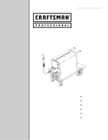
Operator’s Manual
210 AMP
MIG WELDER
Model No. 117.205710
CAUTION:
Before using welder, read this
manual and follow all its Safety
Rules and Operating Instructions.
w
Safety Rules
w
Installation
w
Operation
w
Maintenance
w
Parts
w
Español
Sears, Roebuck and Co., Hoffman Estates, IL 60179 U.S.A.
OM-194 199E
April 2001
Visit the Craftsman web page: www.sears.com/craftsman