Cub Cadet RZT S 42 RZT S 42 Operator's Manual - Page 25
Battery Removal, Charging the Battery, Servicing Electrical System
 |
View all Cub Cadet RZT S 42 manuals
Add to My Manuals
Save this manual to your list of manuals |
Page 25 highlights
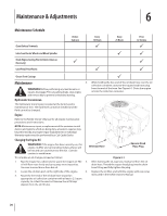
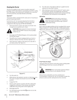
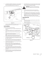
Service 7 NOTE: This Operator's Manual covers several models. Tractor features may vary by model. Not all features in this manual are applicable to all tractor models and the tractor depicted may differ from yours. WARNING! Before performing any service, place the PTO switch in the "OFF" position, engage the parking brake lever, turn the ignition key to the "OFF" position and remove the key from the switch. Battery Removal WARNING! Battery posts, terminals and related accessories contain lead and lead compounds. Wash hands after handling. Charging the Battery Test and, if necessary, recharge the battery after the tractor has been stored for a period of time. • A voltmeter or load tester should read 12.6 volts (DC) or higher across the battery terminals. See Figure 7-2. Voltmeter Reading 12.7 12.4 12.2 12.0 State of Charge 100% 75% 50% 25% Charging Time Full Charge 90 Min. 180 Min. 280 Min. The battery is located beneath the seat frame. To remove the battery: 1. Remove the hex washer screw securing the battery hold- down bracket to the frame. Then flip the battery holddown bracket up to free the battery. See Figure 7-1. Hex Washer Screw Figure 7-2 • Charge the battery with a 12-volt battery charger at a MAXIMUM rate of 10 amps. Servicing Electrical System A fuse is installed to protect the tractor's electrical system from damage caused by excessive amperage. Always use the same capacity fuse for replacement. If the electrical system does not function, check for a blown fuse. If you have a recurring problem with blown fuses, have the tractor's electrical system checked by your Cub Cadet Service Dealer. Relays and Switches There are several safety switches in the electrical system. If a function of the safety interlock system described earlier is not functioning properly, have the electrical system checked by your Cub Cadet Service Dealer. Battery Hold-Down Bracket Figure 7-1 2. Remove the hex cap screw and sems nut securing the black negative battery lead to the negative battery post (marked NEG). Move the cable away from the negative battery post. 3. Remove the hex cap screw and sems nut securing the red positive battery lead to the positive battery post (marked POS). 4. Carefully lift the battery out of the tractor. 5. Install the battery by repeating the above steps in the reverse order. WARNING! Always connect the positive lead to the battery before connecting the negative lead. This will prevent sparking or possible injury from an electrical short caused by contacting the tractor body with tools being used to connect the cables. 25
-
 1
1 -
2
-
3
-
4
-
5
-
6
-
7
-
8
-
9
-
10
-
11
-
12
-
13
-
14
-
15
-
16
-
17
-
18
-
19
-
 20
20 -
 21
21 -
 22
22 -
 23
23 -
 24
24 -
 25
25 -
 26
26 -
 27
27 -
 28
28 -
 29
29 -
 30
30 -
31
-
32
-
33
-
34
-
35
-
36
-
37
-
38
-
39
-
40
-
41
-
42
-
43
-
44
-
45
-
46
-
47
-
48
-
49
-
50
-
51
-
52
-
53
-
54
-
55
-
56
-
57
-
58
-
59
-
60
-
61
-
62
-
63
-
64
-
65
-
66
-
67
-
68
-
69
-
70
-
71
-
72
-
73
-
74
-
75
-
76
 |
 |