Cub Cadet RZT S 42 RZT S 42 Operator's Manual - Page 29
Mower Blade Care - blade removal
 |
View all Cub Cadet RZT S 42 manuals
Add to My Manuals
Save this manual to your list of manuals |
Page 29 highlights
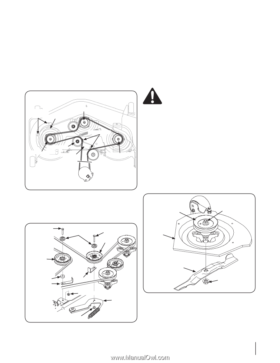
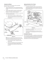
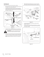
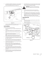
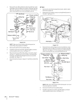
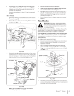
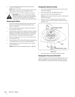
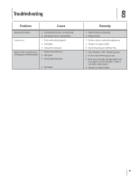
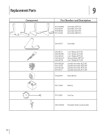
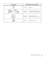
6. Place the belt around the idler pulleys removed in step 3 with the "V" side facing in. Once in place, reinstall all the hardware and tighten the flange lock nut to secure the assembly. See Figure 7-10. 7. Route the belt as shown in Figure 7-10 and then reinstall the deck. 50" & 54" Decks 1. Remove the deck from beneath the tractor, (refer to Deck Removal on page 26). 2. Remove the hex washer screws securing the belt covers to the deck. See Figure 7-11. Hex Washer Screws Spindle Pulley Belt Cover Belt Guards Idler Pulley Spindle Pulley Idler Arm Spindle Pulley Figure 7-11 3. Remove the two idler pulleys by removing the hex screws and flange lock nuts that secure them to the deck and the idler arm. See Figure 7-12. Do not lose any of the hardware when removing the hex screw and flange lock nut. 4. Remove the belt from the spindle pulleys. 5. Install the new belt around the spindle pulleys as shown and reinstall the belt covers. See Figure 7-11. 6. Place the belt around the idler pulleys removed in step 3 with the "V" side facing in. Once in place, reinstall all the hardware and tighten the flange lock nut to secure the assembly. See Figure 7-12. 7. Route the belt as shown in Figure 7-12 and then reinstall the deck. Mower Blade Care WARNING! Protect your hands by using heavy gloves when handling the blades. When servicing the mower deck, be careful not to cut yourself on the sharpened blades. The cutting blades must be kept sharp at all times. Sharpen the cutting edges of the blades evenly so that the blades remain balanced and the same angle of sharpness is maintained. If the cutting edge of a blade has already been sharpened many times, or if any metal separation is present, it is recommended that new blades be installed. New blades are available at your authorized dealer. The blades may be removed as follows. 1. Remove the deck from beneath the tractor, (refer to Deck Removal on page 26) then gently flip the deck over to expose its underside. 2. Use a 15⁄16" wrench to hold the flange nut on top of the spindle assembly and using another 15⁄16" wrench on the flange nut securing the blade the blade, remove the blade. See Figure 7-13. Spindle Assembly Flange Nut Hex Screw Pulley Cap Hex Screw Idler Pulley Deck Idler Pulley Spacer Belt Guard Belt Guard Flange Lock Nut Idler Arm Flange Lock Nut Figure 7-12 NOTE: Take note of the position of the belt guards to ensure they are properly re-installed. Blade Flange Nut Figure 7-13 3. A block of wood may be placed between the deck housing and the cutting edge of the blade to help in breaking loose the flange nut securing the blade. Section 7 - Service 29
-
 1
1 -
2
-
3
-
4
-
5
-
6
-
7
-
8
-
9
-
10
-
11
-
12
-
13
-
14
-
15
-
16
-
17
-
18
-
19
-
20
-
21
-
22
-
23
-
 24
24 -
 25
25 -
 26
26 -
 27
27 -
 28
28 -
 29
29 -
 30
30 -
 31
31 -
 32
32 -
 33
33 -
 34
34 -
35
-
36
-
37
-
38
-
39
-
40
-
41
-
42
-
43
-
44
-
45
-
46
-
47
-
48
-
49
-
50
-
51
-
52
-
53
-
54
-
55
-
56
-
57
-
58
-
59
-
60
-
61
-
62
-
63
-
64
-
65
-
66
-
67
-
68
-
69
-
70
-
71
-
72
-
73
-
74
-
75
-
76
 |
 |