D-Link DCS-5605 Product Manual - Page 7
Hardware Overview
 |
UPC - 790069334870
View all D-Link DCS-5605 manuals
Add to My Manuals
Save this manual to your list of manuals |
Page 7 highlights
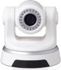
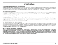
Hardware Overview Rear 1 Micro SD Port Insert a Micro SD memory card to save data from the camera. 2 WPS (DCS-5635 Only) Press the WPS button to automatically connect to a WPS-enabled wireless router or access point and establish connectivity. 3 Power Receptor Plug in the supplied power adapter to an outlet. 4 Ethernet Port Connect an Ethernet cable to a router, switch, or computer. The Ethernet port can also be used to power the camera using a PoE switch (DCS-5605 only). The camera provides a terminal block with two pairs of connectors situated on the back panel. One 5 I/O Connector pair is for input and the other is for output. The I/O connectors provide the physical interface to send 9 and receive digital signals to a variety of external alarm devices. Please refer to the I/O Connector section in this manual for detailed information. Plug the included A/V cable into the A/V out 6 Video/Audio Line-Out Port connector to use the camera with a television or 1 VCR, or connect to speakers. 8 7 External Microphone Port Insert an external microphone to record audio. 8 Reset Button Press and hold for 10 seconds to reset the camera back to the default settings. 23 4 5 6 7 Antenna 9 connector(DCS-5635 Only) Connects to the wireless antennas D-Link DCS-5605/DCS-5635 User Manual 6
-
 1
1 -
 2
2 -
 3
3 -
 4
4 -
 5
5 -
 6
6 -
 7
7 -
 8
8 -
 9
9 -
 10
10 -
 11
11 -
 12
12 -
13
-
14
-
15
-
16
-
17
-
18
-
19
-
20
-
21
-
22
-
23
-
24
-
25
-
26
-
27
-
28
-
29
-
30
-
31
-
32
-
33
-
34
-
35
-
36
-
37
-
38
-
39
-
40
-
41
-
42
-
43
-
44
-
45
-
46
-
47
-
48
-
49
-
50
-
51
-
52
-
53
-
54
-
55
-
56
-
57
-
58
-
59
-
60
-
61
-
62
-
63
-
64
-
65
-
66
-
67
-
68
-
69
-
70
-
71
-
72
-
73
-
74
-
75
-
76
-
77
-
78
-
79
-
80
-
81
-
82
-
83
-
84
-
85
-
86
-
87
-
88
-
89
-
90
-
91
-
92
-
93
-
94
-
95
-
96
-
97
-
98
 |
 |
