D-Link DES-5664TX User Guide - Page 30
CPU Module
 |
UPC - 790069226427
View all D-Link DES-5664TX manuals
Add to My Manuals
Save this manual to your list of manuals |
Page 30 highlights
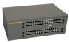
Fast Ethernet Switching System User's Guide CPU Module The CPU module, displayed in Figure 10, is in the middle of the chassis. This is the only slot it will work in. If it is not middle of the chassis, the DES-5600 will not work. See Table 2: Power LED for an explanation of the LEDs on the CPU module. Each LED is explained in detail. Po w e r Module Fail Utilization OK Fault Module Fail 12 3 4 Figure 10: CPU Module Power The power LED lights when the DES-5600 is powered on. The purpose is to confirm that the DES-5600 is getting adequate power. See Table 2: Power LED. Table 2: Power LED Status On Off Color Green Dark Meaning DES-5600 is powered on DES-5600 is powered off, check power cable and connection Status The OK indicates the status of the switch. The OK LED is green when the switch is okay. The Fault LED is amber if there is problem. Utilization The Utilization LED indicates the utilization of the DES-5600's CPU. It increments from left to right. The higher the number the greater the switch utilization. Module Fail Indicates the number of the module that has failed. LEDs 23
-
 1
1 -
2
-
3
-
4
-
5
-
6
-
7
-
8
-
9
-
10
-
11
-
12
-
13
-
14
-
15
-
16
-
17
-
18
-
19
-
20
-
21
-
22
-
23
-
24
-
 25
25 -
 26
26 -
 27
27 -
 28
28 -
 29
29 -
 30
30 -
 31
31 -
 32
32 -
 33
33 -
 34
34 -
 35
35 -
36
-
37
-
38
-
39
-
40
-
41
-
42
-
43
-
44
-
45
-
46
-
47
-
48
-
49
-
50
-
51
-
52
-
53
-
54
-
55
-
56
-
57
-
58
-
59
-
60
-
61
-
62
-
63
-
64
-
65
-
66
-
67
-
68
-
69
-
70
-
71
-
72
-
73
-
74
-
75
-
76
-
77
-
78
-
79
-
80
-
81
-
82
-
83
-
84
-
85
-
86
-
87
-
88
-
89
-
90
-
91
-
92
-
93
-
94
-
95
-
96
-
97
-
98
-
99
-
100
-
101
-
102
-
103
-
104
-
105
-
106
-
107
-
108
-
109
-
110
-
111
-
112
-
113
-
114
-
115
-
116
-
117
-
118
-
119
-
120
-
121
-
122
-
123
-
124
-
125
-
126
-
127
-
128
-
129
-
130
-
131
-
132
-
133
 |
 |
