D-Link DGS-1224T Product Manual - Page 7
Step 3 – Plugging in the AC Power Cord, Power Failure
 |
UPC - 790069264467
View all D-Link DGS-1224T manuals
Add to My Manuals
Save this manual to your list of manuals |
Page 7 highlights
1 Hardware Installation D-Link Web Smart Switch User Manual Then, use the screws provided with the equipment rack to mount the switch in the rack. Figure 3 - Mount the Switch in the rack or chassis Step 3 - Plugging in the AC Power Cord Users may now connect the AC power cord into the rear of the switch and to an electrical outlet (preferably one that is grounded and surge protected). Figure 4 -Plugging the switch into an outlet Power Failure As a precaution, the switch should be unplugged in case of power failure. When power is resumed, plug the switch back in. 3
-
 1
1 -
 2
2 -
 3
3 -
 4
4 -
 5
5 -
 6
6 -
 7
7 -
 8
8 -
 9
9 -
 10
10 -
 11
11 -
 12
12 -
13
-
14
-
15
-
16
-
17
-
18
-
19
-
20
-
21
-
22
-
23
-
24
-
25
-
26
-
27
-
28
-
29
-
30
-
31
-
32
-
33
-
34
-
35
-
36
-
37
-
38
-
39
-
40
-
41
-
42
-
43
-
44
-
45
-
46
-
47
-
48
-
49
-
50
-
51
-
52
 |
 |

1
Hardware Installation
D-Link Web Smart Switch User Manual
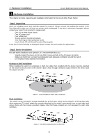
Then, use the screws provided with the equipment rack to mount the switch in the rack.
Figure 3 – Mount the Switch in the rack or chassis
Step 3 – Plugging in the AC Power Cord
Users may now connect the AC power cord into the rear of the switch and to an electrical outlet (preferably
one that is grounded and surge protected).
Figure 4 –Plugging the switch into an outlet
Power Failure
As a precaution, the switch should be unplugged in case of power failure. When power is resumed, plug the
switch back in.
3