Dell Alienware Area-51 R4 Alienware Area-51 R5 Service Manual - Page 96
Remove the two screws #6-32x6 from inside, securing the base panel to the right side of the chassis.
 |
View all Dell Alienware Area-51 R4 manuals
Add to My Manuals
Save this manual to your list of manuals |
Page 96 highlights
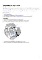
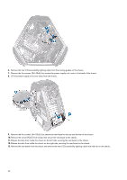
a. tabs (2) b. screws (3) c. chassis 4. Remove the two screws (#6-32x6) from inside, securing the base panel to the right side of the chassis. 5. Release the tabs from inside the chassis on the right side, securing the base panel to the right side of the chassis. a. screws (2) 96
-
 1
1 -
2
-
3
-
4
-
5
-
6
-
7
-
8
-
9
-
10
-
11
-
12
-
13
-
14
-
15
-
16
-
17
-
18
-
19
-
20
-
21
-
22
-
23
-
24
-
25
-
26
-
27
-
28
-
29
-
30
-
31
-
32
-
33
-
34
-
35
-
36
-
37
-
38
-
39
-
40
-
41
-
42
-
43
-
44
-
45
-
46
-
47
-
48
-
49
-
50
-
51
-
52
-
53
-
54
-
55
-
56
-
57
-
58
-
59
-
60
-
61
-
62
-
63
-
64
-
65
-
66
-
67
-
68
-
69
-
70
-
71
-
72
-
73
-
74
-
75
-
76
-
77
-
78
-
79
-
80
-
81
-
82
-
83
-
84
-
85
-
86
-
87
-
88
-
89
-
90
-
 91
91 -
 92
92 -
 93
93 -
 94
94 -
 95
95 -
 96
96 -
 97
97 -
 98
98 -
 99
99 -
 100
100 -
 101
101 -
102
-
103
-
104
-
105
-
106
-
107
-
108
-
109
-
110
-
111
-
112
-
113
-
114
-
115
-
116
-
117
-
118
-
119
-
120
-
121
 |
 |

a.
tabs (2)
b.
screws (3)
c.
chassis
4.
Remove the two screws (#6-32x6) from inside, securing the base panel to the right side of the chassis.
5.
Release the tabs from inside the chassis on the right side, securing the base panel to the right side of the chassis.
a.
screws (2)
96