Dell E521 Owner's Manual - Page 66
Memory, Memory Installation Guidelines
 |
UPC - 015561600385
View all Dell E521 manuals
Add to My Manuals
Save this manual to your list of manuals |
Page 66 highlights
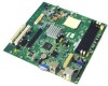
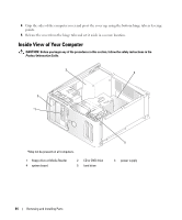
13 video connector (VIDEO1) 16 PCI Express x16 connector (SLOT1) 19 PCI connector (SLOT3) 22 floppy drive connector (FLOPPY1) 14 battery socket (BT1) 17 standby power indicator (AUX_PWR_LED) 20 PCI connector (SLOT4) 15 Internal USB connector (USB1) 18 PCI Express x1 connector (SLOT2) 21 password jumper (PSWD) Memory You can increase your computer memory by installing memory modules on the system board. Your computer supports DDR2 memory. For additional information on the type of memory supported by your computer, see "Memory" on page 107. NOTICE: Do not install ECC or buffered memory modules. Only unbuffered, non-ECC memory is supported. Memory Installation Guidelines • DIMM connectors must be populated in numerical order beginning with connectors DIMM_1 and DIMM_2, then connectors DIMM_3 and DIMM_4. If a single DIMM is installed, you must install it in connector DIMM_1. • For best performance, memory modules should be installed in pairs of matched memory size, speed, and technology. If the memory modules are not installed in matched pairs, the computer will operate, but with a slight reduction in performance. (See the label on the module to determine the module's capacity.) For example, if you install a mixed pair of DDR2 533-MHz and DDR2 667-MHz memory, the modules function at the slowest speed installed. 66 Removing and Installing Parts
-
 1
1 -
2
-
3
-
4
-
5
-
6
-
7
-
8
-
9
-
10
-
11
-
12
-
13
-
14
-
15
-
16
-
17
-
18
-
19
-
20
-
21
-
22
-
23
-
24
-
25
-
26
-
27
-
28
-
29
-
30
-
31
-
32
-
33
-
34
-
35
-
36
-
37
-
38
-
39
-
40
-
41
-
42
-
43
-
44
-
45
-
46
-
47
-
48
-
49
-
50
-
51
-
52
-
53
-
54
-
55
-
56
-
57
-
58
-
59
-
60
-
 61
61 -
 62
62 -
 63
63 -
 64
64 -
 65
65 -
 66
66 -
 67
67 -
 68
68 -
 69
69 -
 70
70 -
 71
71 -
72
-
73
-
74
-
75
-
76
-
77
-
78
-
79
-
80
-
81
-
82
-
83
-
84
-
85
-
86
-
87
-
88
-
89
-
90
-
91
-
92
-
93
-
94
-
95
-
96
-
97
-
98
-
99
-
100
-
101
-
102
-
103
-
104
-
105
-
106
-
107
-
108
-
109
-
110
-
111
-
112
-
113
-
114
-
115
-
116
-
117
-
118
-
119
-
120
-
121
-
122
-
123
-
124
-
125
-
126
-
127
-
128
-
129
-
130
-
131
-
132
-
133
-
134
-
135
-
136
-
137
-
138
-
139
-
140
-
141
-
142
-
143
-
144
-
145
-
146
-
147
-
148
-
149
-
150
-
151
-
152
-
153
-
154
-
155
-
156
-
157
-
158
 |
 |
