Dell External OEMR R410 Technical Guide - Page 17
NIC Indicators, Side Views
 |
View all Dell External OEMR R410 manuals
Add to My Manuals
Save this manual to your list of manuals |
Page 17 highlights
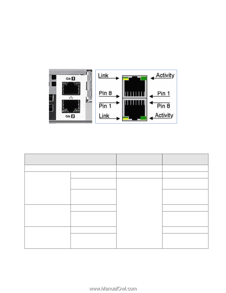
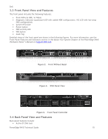
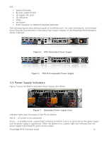
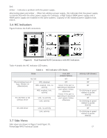
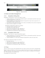
Dell Amber - Indicates a problem with the power supply. Alternating green and amber - When hot-adding a power supply, this indicates that the power supply is mismatched with the other power supply (for example, a High-Output 500W power supply and a 400W power supply are installed in the same system). Capacity of the installed power supplies must match. 3.6 NIC Indicators Figure 8 shows the RJ45 connectors. Figure 8. Dual-Stacked RJ45 Connectors with NIC Indicators Table 4 details the NIC indicator LED states. Table 4. NIC Indicator LED States State No link D0uninitalized (out of box), D3cold, S4 (hibernation) WOL disabled WOL enabled, link, no activity WOL enabled, link, activity Pre-OS POST or OS without driver Link, no activity Link, activity Link LED (Green/Yellow) Off Off Green if the port is operating at maximum port speed; Yellow otherwise Green if the port is operating at maximum port speed; Yellow otherwise OS with driver Link, no activity Link, activity 3.7 Side Views Side views are shown in Figure 9 and Figure 10. PowerEdge R410 Technical Guide Activity LED (Green) Off Off Off On (blinking at speed related to packet density) Off On (blinking at speed related to packet density) Off On (blinking at speed related to packet density) 17
-
 1
1 -
2
-
3
-
4
-
5
-
6
-
7
-
8
-
9
-
10
-
11
-
 12
12 -
 13
13 -
 14
14 -
 15
15 -
 16
16 -
 17
17 -
 18
18 -
 19
19 -
 20
20 -
 21
21 -
 22
22 -
23
-
24
-
25
-
26
-
27
-
28
-
29
-
30
-
31
-
32
-
33
-
34
-
35
-
36
-
37
-
38
-
39
-
40
-
41
-
42
-
43
-
44
-
45
-
46
-
47
-
48
-
49
-
50
-
51
-
52
-
53
-
54
-
55
-
56
-
57
-
58
 |
 |