Dell External OEMR R410 Technical Guide - Page 45
Cable Management Arm CMA
 |
View all Dell External OEMR R410 manuals
Add to My Manuals
Save this manual to your list of manuals |
Page 45 highlights
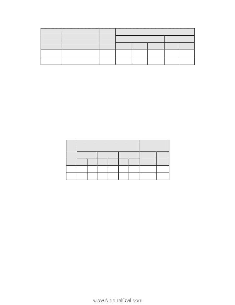
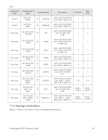
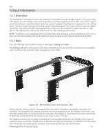
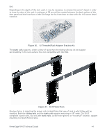
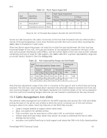
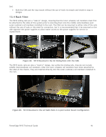
Dell Table 14. Rack Types Supported Rail Mounting Identifier Interface Rail Type Rack Types Supported 4-Post 2-Post Square Round Thread Flush Center A3 ReadyRails™ Sliding √ √ √* X X A4 ReadyRails/Generic Static √ √ √ √ √ *Requires the 1U Threaded Rack Adapter Brackets Kit (Dell PN 8Y19G) Screws are not included in the static rail kit due to the fact that threaded racks are offered with a variety of thread designations. Users must therefore provide their own screws when mounting the static rails in threaded or 2-post racks. Other key factors governing proper rail selection include the spacing between the front and rear mounting flanges of the rack, the type and location of any equipment mounted in the back of the rack such as power distribution units (PDUs), and the overall depth of the rack. Due to their reduced complexity and lack of need for CMA support, the static rails offer a greater adjustability range and an overall smaller footprint than the sliding rails. Table 15. Rail Adjustability Range and Rail Depth Rail ID Rail Adjustability Range (mm) Rail Depth (mm) Square Round Threaded without with Min Max Min Max Min Max CMA CMA A3 686 883 672 876 651 897 714 835 A4 608 879 594 872 604 890 622 - Note that the adjustment range of the rails is a function of the type of rack in which they are being mounted. The min-max values listed above represent the allowable distance between the front and rear mounting flanges in the rack. Rail depth represents the minimum depth of the rail as measured from the rack front mounting flanges when the rail rear bracket is positioned all the way forward. 13.3 Cable Management Arm (CMA) The optional cable management arm (CMA) for the R410 organizes and secures the cords and cables exiting the back of the server and unfolds to allow the server to extend out of the rack without having to detach the cables. Some key features of the R410 CMA include: Large U-shaped baskets to support dense cable loads Open vent pattern for optimal airflow Fully reversible (can be mounted on either side) with no conversion required Utilizes hook-and-loop straps rather than plastic tie wraps to eliminate the risk of cable damage during cycling Includes a low profile fixed tray to both support and retain the CMA in its fully closed position PowerEdge R410 Technical Guide 45
-
 1
1 -
2
-
3
-
4
-
5
-
6
-
7
-
8
-
9
-
10
-
11
-
12
-
13
-
14
-
15
-
16
-
17
-
18
-
19
-
20
-
21
-
22
-
23
-
24
-
25
-
26
-
27
-
28
-
29
-
30
-
31
-
32
-
33
-
34
-
35
-
36
-
37
-
38
-
39
-
 40
40 -
 41
41 -
 42
42 -
 43
43 -
 44
44 -
 45
45 -
 46
46 -
 47
47 -
 48
48 -
 49
49 -
 50
50 -
51
-
52
-
53
-
54
-
55
-
56
-
57
-
58
 |
 |