Dell Latitude D610 Service Manual - Page 14
Display Panel
 |
View all Dell Latitude D610 manuals
Add to My Manuals
Save this manual to your list of manuals |
Page 14 highlights
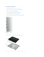
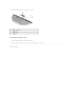
6. Remove the six M2.5 x 5-mm screws located on the front of the bezel. 1 display bezel 2 display panel 3 display bumpers (6) 4 M2.5 x 5-mm screws (6) NOTICE: Carefully separate the bezel from the top cover to avoid damage to the bezel. 7. Starting at the bottom of the display panel (by the Dell™ logo), use your fingers to separate the bezel from the top cover by lifting the inside edge of the bezel and rotating away from the top cover. NOTE: Follow the same procedure on all four sides of the display bezel until it snaps completely off. Installing the Display Bezel 1. Starting at any corner, use your fingers to gently snap the bezel in place securing the display panel. 2. Tighten the six M2.5 x 5-mm screws on the front of the bezel. 3. Replace the six display bumpers around the display assembly. Display Panel CAUTION: Before you begin any of the procedures in this section, follow the safety instructions in the Product Information Guide. NOTICE: To avoid electrostatic discharge, ground yourself by using a wrist grounding strap or by touching an unpainted metal surface on the computer.
-
 1
1 -
2
-
3
-
4
-
5
-
6
-
7
-
8
-
 9
9 -
 10
10 -
 11
11 -
 12
12 -
 13
13 -
 14
14 -
 15
15 -
 16
16 -
 17
17 -
 18
18 -
 19
19 -
20
-
21
-
22
-
23
-
24
-
25
-
26
-
27
-
28
-
29
-
30
-
31
-
32
-
33
-
34
-
35
-
36
-
37
-
38
-
39
-
40
-
41
-
42
-
43
-
44
-
45
-
46
-
47
 |
 |
