Dell Latitude D610 Service Manual - Page 35
System Board
 |
View all Dell Latitude D610 manuals
Add to My Manuals
Save this manual to your list of manuals |
Page 35 highlights
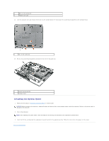
Back to Contents Page System Board Dell™ Latitude™ D610 Service Manual Removing the System Board Installing the System Board Removing the System Board CAUTION: Before you begin any of the procedures in this section, follow the safety instructions in the Product Information Guide. NOTICE: To avoid electrostatic discharge, ground yourself by using a wrist grounding strap or by periodically touching an unpainted metal surface (such as the back panel) on the computer. The system board's BIOS chip contains the Service Tag, which is also visible on a barcode label on the bottom of the computer. The replacement kit for the system board includes a CD that provides a utility for transferring the Service Tag to the replacement system board. NOTICE: Disconnect the computer and any attached devices from electrical outlets, and remove any installed batteries. NOTICE: To avoid electrostatic discharge, ground yourself by using a wrist grounding strap or by touching an unpainted metal surface on the computer. 1. Follow the instructions in "Preparing to Work Inside the Computer." 2. Remove the center control cover (see "Removing the Center Control Cover"). 3. Remove the keyboard (see "Removing the Keyboard"). 4. Remove the display assembly (see "Removing the Display Assembly"). 5. Remove the palm rest (see "Removing the Palm Rest"). 6. Remove the fan (see "Removing the Fan"). 7. Remove the microprocessor thermal-cooling assembly (see "Removing the Microprocessor Thermal-Cooling Assembly"). 8. Remove the microprocessor (see "Removing the Microprocessor Module"). 9. Remove the speaker assembly (see "Removing the Speaker Assembly"). 10. Remove the internal card with Bluetooth® wireless technology (see step #4). 11. Remove the four M2x3 screws that secure the PCMCIA card cage to the system board.
-
 1
1 -
2
-
3
-
4
-
5
-
6
-
7
-
8
-
9
-
10
-
11
-
12
-
13
-
14
-
15
-
16
-
17
-
18
-
19
-
20
-
21
-
22
-
23
-
24
-
25
-
26
-
27
-
28
-
29
-
 30
30 -
 31
31 -
 32
32 -
 33
33 -
 34
34 -
 35
35 -
 36
36 -
 37
37 -
 38
38 -
 39
39 -
 40
40 -
41
-
42
-
43
-
44
-
45
-
46
-
47
 |
 |