Dell Latitude D610 Service Manual - Page 30
Installing the Palm Rest
 |
View all Dell Latitude D610 manuals
Add to My Manuals
Save this manual to your list of manuals |
Page 30 highlights
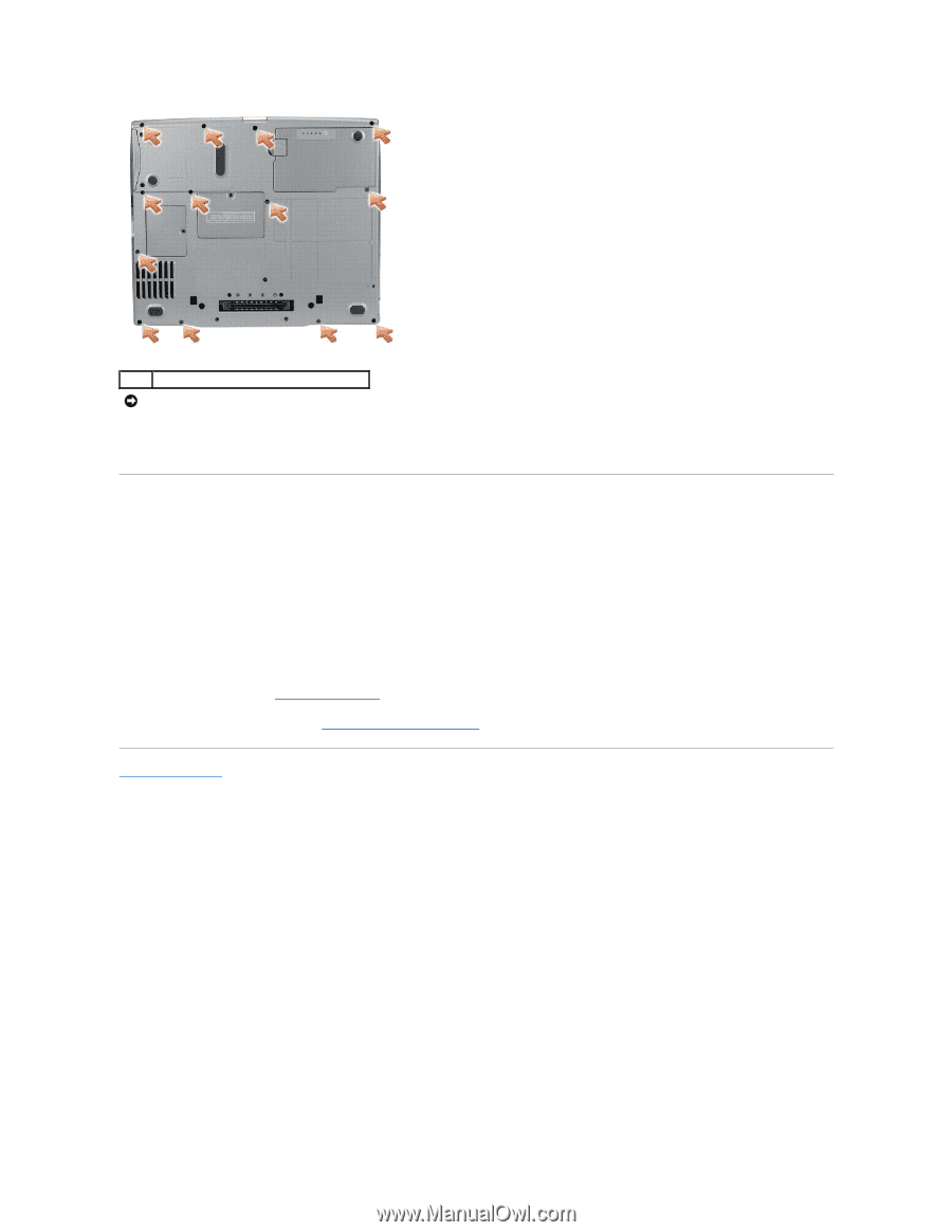
1 M2.5 x 8-mm screws (13) NOTICE: Carefully separate the palm rest from the computer base to avoid damage to the palm rest. 8. Starting at the back center of the palm rest, use your fingers to separate the palm rest from the computer base by lifting the inside of the palm rest while pushing in on the outside. Installing the Palm Rest 1. Align the palm rest with the computer base and snap into place. 2. Connect the touch pad cable to the connector on the system board. 3. Replace the three M2.5 x 5-mm screws on the top of the palm rest. 4. Turn the computer over and replace the thirteen M2.5 x 8-mm screws. 5. Replace the display assembly. 6. Replace the keyboard (see "Installing the Keyboard"). 7. Replace the center control cover (see "Installing the Center Control Cover"). Back to Contents Page
-
 1
1 -
2
-
3
-
4
-
5
-
6
-
7
-
8
-
9
-
10
-
11
-
12
-
13
-
14
-
15
-
16
-
17
-
18
-
19
-
20
-
21
-
22
-
23
-
24
-
 25
25 -
 26
26 -
 27
27 -
 28
28 -
 29
29 -
 30
30 -
 31
31 -
 32
32 -
 33
33 -
 34
34 -
 35
35 -
36
-
37
-
38
-
39
-
40
-
41
-
42
-
43
-
44
-
45
-
46
-
47
 |
 |