Dell Latitude D610 Service Manual - Page 3
Recommended Tools, Computer Orientation, Screw Identification
 |
View all Dell Latitude D610 manuals
Add to My Manuals
Save this manual to your list of manuals |
Page 3 highlights
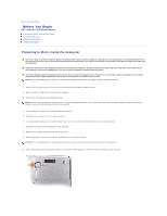
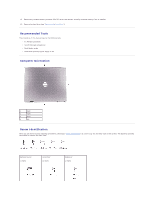
11. Remove any installed memory modules, Mini PCI cards, and devices, including a second battery if one is installed. 12. Remove the hard drive (see "Removing the Hard Drive"). Recommended Tools The procedures in this manual require the following tools: l #1 Phillips screwdriver l ¼-inch flat-blade screwdriver l Small plastic scribe l Flash BIOS update program floppy or CD Computer Orientation 1 back 2 right 3 front 4 left Screw Identification When you are removing and replacing components, photocopy "Screw Identification" as a tool to lay out and keep track of the screws. The placemat provides the number of screws and their sizes. Optional Device: (1 each) Hard Drive: (2 each) Keyboard: (2 each)
-
 1
1 -
 2
2 -
 3
3 -
 4
4 -
 5
5 -
 6
6 -
 7
7 -
 8
8 -
 9
9 -
10
-
11
-
12
-
13
-
14
-
15
-
16
-
17
-
18
-
19
-
20
-
21
-
22
-
23
-
24
-
25
-
26
-
27
-
28
-
29
-
30
-
31
-
32
-
33
-
34
-
35
-
36
-
37
-
38
-
39
-
40
-
41
-
42
-
43
-
44
-
45
-
46
-
47
 |
 |

11.
Remove any installed memory modules, Mini PCI cards, and devices, including a second battery if one is installed.
12.
Remove the hard drive (see "
Removing the Hard Drive
").
Recommended Tools
The procedures in this manual require the following tools:
l
#1 Phillips screwdriver
l
¼
-inch flat-blade screwdriver
l
Small plastic scribe
l
Flash BIOS update program floppy or CD
Computer Orientation
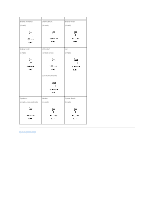
Screw Identification
When you are removing and replacing components, photocopy "
Screw Identification
" as a tool to lay out and keep track of the screws. The placemat provides
the number of screws and their sizes.
1
back
2
right
3
front
4
left
Optional Device:
(1 each)
Hard Drive:
(2 each)
Keyboard:
(2 each)