Dell Latitude D610 Service Manual - Page 16
Display Latch
 |
View all Dell Latitude D610 manuals
Add to My Manuals
Save this manual to your list of manuals |
Page 16 highlights
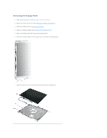
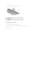
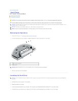
1 display panel 2 top cover 3 M2 x 3-mm screws (4) 8. Remove the display panel from the top cover. 9. Use the pull-tab to disconnect the bottom flex-cable connector from the inverter connector. 1 top flex-cable connector 2 top display-cable connector 3 pull-tab on bottom flex-cable connector 10. Press in both sides of the top display cable connector, and pull the display cable connector away from the top flex-cable connector. Installing the Display Panel 1. Connect the top display cable connector to the top flex-cable connector. 2. Connect the bottom flex-cable connector to the inverter connector. 3. Replace the display panel inside the top cover. 4. Tighten the four M2 x 3-mm screws (two on each side) around the display panel. 5. Replace the display bezel (see "Installing the Display Bezel"). Display Latch NOTICE: Disconnect the computer and any attached devices from electrical outlets, and remove any installed batteries. NOTICE: To avoid electrostatic discharge, ground yourself by using a wrist grounding strap or by touching an unpainted metal surface on the computer. Removing the Display Latch 1. Follow the instructions in "Preparing to Work Inside the Computer." 2. Remove the center control cover (see "Removing the Center Control Cover"). 3. Remove the keyboard (see "Removing the Keyboard"). 4. Remove the display assembly (see "Removing the Display Assembly"). 5. Remove the display bezel (see "Removing the Display Bezel"). 6. Remove the M2.5 x 5-mm screw that secures the display latch to the top cover.
-
 1
1 -
2
-
3
-
4
-
5
-
6
-
7
-
8
-
9
-
10
-
 11
11 -
 12
12 -
 13
13 -
 14
14 -
 15
15 -
 16
16 -
 17
17 -
 18
18 -
 19
19 -
 20
20 -
 21
21 -
22
-
23
-
24
-
25
-
26
-
27
-
28
-
29
-
30
-
31
-
32
-
33
-
34
-
35
-
36
-
37
-
38
-
39
-
40
-
41
-
42
-
43
-
44
-
45
-
46
-
47
 |
 |
